Toyota Sienna Service Manual: Disassembly
1. REMOVE STEERING INTERMEDIATE SHAFT ASSEMBLY

(a) Align the matchmarks on the steering intermediate shaft assembly and main shaft.
(b) Remove the bolt and steering intermediate shaft assembly.
2. REMOVE KEY CYLINDER LIGHT ASSEMBLY (w/o Engine Immobiliser System)
3. REMOVE TRANSPONDER KEY AMPLIFIER (w/ Engine Immobiliser System)
(a) Widen the claw hanging onto the upper bracket by approx. 1.0 mm (0.039 in.) using a screwdriver.
(b) Pull the transponder key amplifier toward the rear of the vehicle with the claw open.
NOTICE: Take care not to use excessive force to prevent the case from being damaged.
4. REMOVE STEERING COLUMN BRACKET ASSEMBLY UPPER
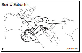
(a) Using a centering punch, mark the center of the 2 tapered-head bolts.
(b) Using a 3 to 4 mm (0.12 to 0.16 in.) drill, drill a hole into the heads of the 2 bolts.
(c) Using a screw extractor, remove the 2 bolts and steering column upper w/ switch bracket assembly.
5. REMOVE IGNITION SWITCH LOCK CYLINDER ASSEMBLY

(a) Place the ignition switch lock cylinder assembly in the ACC position.
(b) Push down the stop pin with a screwdriver, and pull out the cylinder assembly.
6. REMOVE UN-LOCK WARNING SWITCH ASSEMBLY

(a) Disconnect the un-lock warning switch assembly connector from the ignition or starter switch assembly.
(b) Remove the un-lock warning switch assembly by pushing up the center part and releasing the 2 claws.
(c) Disengage the secondary locking device.
(d) Using a screwdriver, disengage the locking lug of terminals 1 and 2, and pull the terminals out from the rear side of the un-lock warning switch assembly.

7. REMOVE KEY INTER LOCK SOLENOID
(a) Remove the 2 screws and solenoid from the steering column bracket assembly.
8. REMOVE IGNITION OR STARTER SWITCH ASSEMBLY
(a) Remove the 2 screws and ignition or starter switch assembly from the steering column bracket assembly UPR.
 Removal
1. PRECAUTION
HINT:
See page RS-1
2. DISCONNECT BATTERY NEGATIVE TERMINAL
Wait for 90 seconds after disconnecting the battery
terminal to prevent the airbag working.
3. PLACE FRONT WHEELS FACING ...
 Reassembly
1. INSTALL IGNITION OR STARTER SWITCH
ASSEMBLY
(a) Install the ignition or starter switch assembly to the
steering column bracket assembly UPR with the 2
screws.
2. INSTALL KEY INTER LOCK SOLENOI ...
Other materials:
Compressor Solenoid Circuit
DESCRIPTION
In this circuit, the compressor receives a refrigerant compression demand
signal from the A/C amplifier.
Based on this signal, the compressor changes the amount of compressor output.
WIRING DIAGRAM
INSPECTION PROCEDURE
1 INSPECT A/C COMPRESSOR
(a) Disconnect the A/C com ...
Diagnosis system
1. DESCRIPTION
When troubleshooting a vehicle with the diagnosis
system, the only difference from the usual
troubleshooting procedure is connecting the
intelligent tester to the vehicle and reading various
data output from the vehicle's clearance warning
ECU.
The clearance warn ...
Open in Stop Light Switch Circuit
DTC C1249/49 Open in Stop Light Switch Circuit
DESCRIPTION
WIRING DIAGRAM
INSPECTION PROCEDURE
1 CHECK STOP LIGHT SWITCH OPERATION
(a) Check that the stop light comes on when the brake pedal
is depressed and goes off when the brake pedal is
released.
OK
HINT:
Check the stop li ...