Toyota Sienna Service Manual: TC and CG Terminal Circuit
DESCRIPTION
DTC output mode is set by connecting terminals TC and CG of the DLC3.
The DTCs are displayed by the blinking pattern of the ABS warning light.
WIRING DIAGRAM

HINT: When warning lights continue to blink, a ground short in the wiring of terminal TC of the DLC3 or an internal ground short in one or more ECU is suspected.
INSPECTION PROCEDURE
1 INSPECT DLC3 (BETWEEN TC of DLC3 AND CG of DLC3)

(a) Turn the ignition switch to the ON position.
(b) Measure the voltage according to the value(s) in the table below.
Standard voltage


2 CHECK HARNESS AND CONNECTOR (BETWEEN SKID CONTROL ECU AND TC of DLC3)

(a) Turn the ignition switch off.
(b) Disconnect the skid control ECU connector.
(c) Measure the resistance according to the value(s) in the table below.
Standard resistance

REPLACE BRAKE ACTUATOR ASSEMBLY
3 CHECK HARNESS AND CONNECTOR (BETWEEN CG of DLC3 AND BODY GROUND)

(a) Turn the ignition switch off.
(b) Measure the resistance according to the value(s) in the table below.
Standard resistance

4 CHECK HARNESS AND CONNECTOR (BETWEEN SKID CONTROL ECU AND TC of DLC3)

(a) Disconnect the skid control ECU connector.
(b) Measure the resistance according to the value(s) in the table below.
Standard resistance 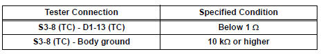


REPLACE BRAKE ACTUATOR ASSEMBLY
 Brake Warning Light does not Come ON
WIRING DIAGRAM
See page BC-52.
INSPECTION PROCEDURE
1 INSPECT BRAKE WARNING LIGHT
(a) Disconnect the skid control ECU connector.
(b) Turn the ignition switch to the on position.
(c) Check th ...
 TS and CG Terminal Circuit
DESCRIPTION
The Test Mode (signal check) circuit detects trouble in the sensor or switch
signal, which cannot be
detected by the DTC check.
Connecting terminals TS and CG of the DLC3 starts the ...
Other materials:
Stowing the flat tire
Take out the strap and tire bag.
Place tire standing up in rear
tub, after putting the tire in the
tire bag.
Clip clasp to outboard hook.
Clip other clasp to center or
opposite hook location.
Pull strap to tighten and secure
tire.
...
Actuator Supply Voltage Circuit / Open
DESCRIPTION
The ECM monitors the output voltage to the throttle actuator. This self-check
ensures that the ECM is
functioning properly. The output voltage is usually 0 V when the ignition switch
is turned off. If the output
voltage is higher than 7 volts when the ignition switch is turned ...
No. 1 Ultrasonic sensor
COMPONENTS
REMOVAL
1. REMOVE FRONT FENDER LINER LH
2. REMOVE FRONT FENDER LINER RH
3. REMOVE FRONT BUMPER COVER
4. REMOVE REAR BUMPER COVER (2)
5. REMOVE NO. 1 ULTRASONIC SENSOR RETAINER
Remove the No. 1 ultrasonic sensor retainer as
shown in the illustration
6. REMOVE ...