Toyota Sienna Service Manual: TS and CG Terminal Circuit
DESCRIPTION
The Test Mode (signal check) circuit detects trouble in the sensor or switch signal, which cannot be detected by the DTC check.
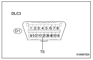
Connecting terminals TS and CG of the DLC3 starts the check.
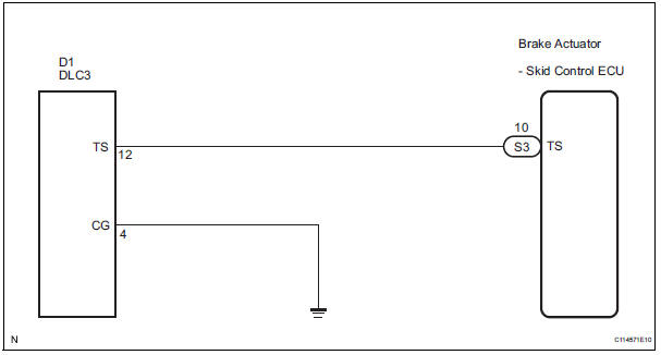
WIRING DIAGRAM
INSPECTION PROCEDURE
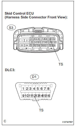
1 CHECK HARNESS AND CONNECTOR (BETWEEN SKID CONTROL ECU AND TS of DLC3)
(a) Turn the ignition switch off.
(b) Disconnect the skid control ECU connector.
(c) Measure the resistance according to the value(s) in the table below.
Standard resistance 

2 CHECK HARNESS AND CONNECTOR (BETWEEN CG of DLC3 AND BODY GROUND)
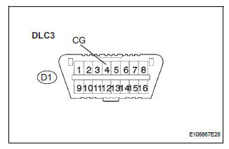
(a) Measure the resistance according to the value(s) in the table below.
Standard resistance


3 CHECK HARNESS AND CONNECTOR (BETWEEN TS of DLC3 AND BODY GROUND)
(a) Measure the resistance according to the value(s) in the table below.
Standard resistance 

REPLACE BRAKE ACTUATOR ASSEMBLY
 TC and CG Terminal Circuit
DESCRIPTION
DTC output mode is set by connecting terminals TC and CG of the DLC3.
The DTCs are displayed by the blinking pattern of the ABS warning light.
WIRING DIAGRAM
HINT:
When warning ...
 Vehicle stability control system
Parts location
...
Other materials:
Installation
1. INSTALL 3 POINT TYPE NO. 2 REAR SEAT BELT ASSEMBLY
Check the degree of tilt when the belt begins to lock
the ELR.
Check that the belt does not lock within 15 of
tilt in all directions but that the belt locks with
over 45 of tilt, when gently moving the
retractor.
If ...
Definition of terms
Term
Definition
Monitor description
Description of what the ecm monitors and how it detects malfunctions
(monitoring purpose and its details).
Related dtcs
Diagnostic codeV
Typical enabling condition
Preconditions that allow the ecm to detect malfunc ...
Vehicle Speed Sensor "A"
DESCRIPTION
The speed sensor detects the wheel speed and sends the appropriate signals to
the skid control ECU.
The skid control ECU converts these wheel speed signals into a 4-pulse signal
and outputs it to the ECM
via the combination meter. The ECM determines the vehicle speed based o ...