Toyota Sienna Service Manual: Vvt sensor
COMPONENTS


ON-VEHICLE INSPECTION
1. CHECK VVT SENSOR OUTPUT VOLTAGE

(a) Turn the ignition switch to the ON position.
(b) Check the voltage between the specified terminal and body ground.
Standard voltage

(c) While turning the crankshaft pulley by hand, measure the voltage between each terminal. Check that the voltage changes between the High range and Low range shown in the table below.
Standard voltage

REMOVAL
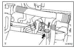
1. REMOVE WINDSHIELD WIPER MOTOR ASSEMBLY HINT: (See page WW-4) 2. REMOVE FRONT OUTER COWL TOP PANEL SUBASSEMBLY (See page EM-27) 3. DRAIN ENGINE COOLANT (See page CO-6) 4. REMOVE V-BANK COVER SUB-ASSEMBLY (See page EM-28) 5. REMOVE NO. 2 AIR CLEANER INLET (See page EM- 28) 6. REMOVE NO. 1 AIR CLEANER INLET (See page EM- 28) 7. REMOVE AIR CLEANER CAP SUB-ASSEMBLY (See page ES-493) 8. REMOVE AIR CLEANER CASE SUB-ASSEMBLY (See page EM-28) 9. REMOVE INTAKE AIR SURGE TANK ASSEMBLY (See page ES-521) 10. REMOVE VVT SENSOR (for Bank 1 Intake Side)

(a) Disconnect the VVT sensor connector.
(b) Remove the bolt and VVT sensor.
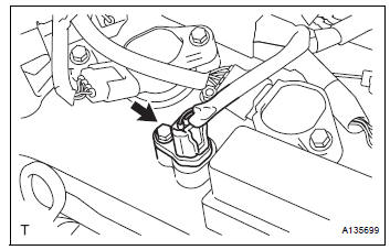
11. REMOVE VVT SENSOR (for Bank 1 Exhaust Side)
(a) Disconnect the VVT sensor connector.
(b) Remove the bolt and VVT sensor.
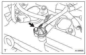
12. REMOVE VVT SENSOR (for Bank 2 Intake Side)

(a) Disconnect the VVT sensor connector.
(b) Remove the bolt and VVT sensor.
13. REMOVE VVT SENSOR (for Bank 2 Exhaust Side)
(a) Disconnect the VVT sensor connector.
(b) Remove the bolt and VVT sensor.
INSTALLATION
1. INSTALL VVT SENSOR (for Bank 2 Exhaust Side)
(a) Install the VVT sensor with the bolt.
Torque: 10 N*m (102 kgf*cm, 7 ft.*lbf) (b) Connect the VVT sensor connector.
2. INSTALL VVT SENSOR (for Bank 2 Intake Side)

(a) Install the VVT sensor with the bolt.
Torque: 10 N*m (102 kgf*cm, 7 ft.*lbf) (b) Connect the VVT sensor connector.
3. INSTALL VVT SENSOR (for Bank 1 Exhaust Side)

(a) Install the VVT sensor with the bolt.
Torque: 10 N*m (102 kgf*cm, 7 ft.*lbf) (b) Connect the VVT sensor connector.
4. INSTALL VVT SENSOR (for Bank 1 Intake Side)
(a) Install the VVT sensor with the bolt.
Torque: 10 N*m (102 kgf*cm, 7 ft.*lbf) (b) Connect the VVT sensor connector.
5. INSTALL INTAKE AIR SURGE TANK ASSEMBLY (See page ES-522) 6. INSTALL AIR CLEANER CASE SUB-ASSEMBLY (See page EM-59) 7. INSTALL AIR CLEANER CAP SUB-ASSEMBLY (See page ES-496) 8. INSTALL NO. 1 AIR CLEANER INLET (See page EM- 59) 9. INSTALL NO. 2 AIR CLEANER INLET (See page EM- 60) 10. ADD ENGINE COOLANT (See page CO-7) 11. INSPECT FOR ENGINE COOLANT LEAK (See page CO-1) 12. INSPECT FOR ENGINE OIL LEAK (See page LU-6) 13. INSTALL V-BANK COVER SUB-ASSEMBLY (See page EM-63) 14. INSTALL FRONT OUTER COWL TOP PANEL SUBASSEMBLY (See page EM-61) 15. INSTALL WINDSHIELD WIPER MOTOR ASSEMBLY
HINT:
(See page WW-5)
 Mass air flow meter
COMPONENTS
ON-VEHICLE INSPECTION
1. INSPECT MASS AIR FLOW METER
NOTICE:
Perform the mass air flow (MAF) meter inspection
by following the procedures below.
Only replace t ...
 Crankshaft position sensor
Components
Removal
1. Remove compressor and magnetic clutch
HINT:
(See page AC-227 )
2. REMOVE CRANKSHAFT POSITION SENSOR
(a) Disconnect the crankshaft position sensor
connector.
(b) R ...
Other materials:
Diagnostic trouble code chart
1. DTC CHECK
If a malfunction code is displayed during the DTC check ,
check the suspected area listed for that code in the table
below, and proceed to the appropriate page.
DIAGNOSTIC TROUBLE CODE CHART
DTC No.
Detection Item
Suspect Area
B1244
Light Se ...
Front wheel alignment
Adjustment
NOTICE:
For vehicles equipped with VSC, if wheel alignment has
been adjusted, and if suspension or underbody
components have been removed/installed or replaced, be
sure to perform the following initialization procedure in
order for the system to function normally:
1. Disconnect the ...
Installation
1. INSTALL TRANSFER EXTENSION HOUSING TYPE T OIL SEAL
(a) Using SST(s), install anew transfer extension
housing type T oil seal to he transfer extension
housing sub-assembly at the position show in the
illustration.
SST 09325-20010
NOTICE:
Do not install the oil seal obliquely.
(b) Apply ...