Toyota Sienna Service Manual: Yaw Rate Sensor Communication Stop Mode
DESCRIPTION
|
Detection Item |
Symptom |
Trouble Area |
| Yaw Rate Sensor Communication Stop Mode |
|
|
WIRING DIAGRAM

INSPECTION PROCEDURE
NOTICE:
- Turn the ignition switch off before measuring the resistances of CAN bus main wires and CAN bus branch wires.
- After the ignition switch is turned off, check that the key reminder warning system and light reminder warning system are not in operation.
- Before measuring the resistance, leave the vehicle as is for at least 1 minute and do not operate the ignition switch, any other switches, or the doors. If any doors need to be opened in order to check connectors, open the doors and leave them open.
HINT: Operating the ignition switch, any switches, or any doors triggers related ECU and sensor communication with the CAN. This communication will cause the resistance value to change.
1 CHECK OPEN IN CAN BUS WIRE (YAW RATE SENSOR BRANCH WIRE)

- Turn the ignition switch off.
- Disconnect the yaw rate sensor connector.
- Measure the resistance according to the value(s) in the table below.
Standard resistance

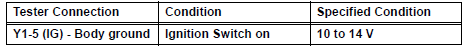
2 CHECK WIRE HARNESS (IG, GND)

- Measure the resistance according to the value(s) in the table below.
Standard resistance

- Measure the voltage according to the value(s) in the table below.
Standard voltage
REPLACE YAW RATE SENSOR
 Steering Angle Sensor Communication Stop Mode
DESCRIPTION
Detection Item
Symptom
Trouble Area
Steering Angle Sensor
Communication Stop
Mode
"Steering angle sensor" is not displayed on ...
 ECM Communication Stop Mode
DESCRIPTION
Detection Item
Symptom
Trouble Area
ECM Communication Stop
Mode
"Engine" is not displayed on the "Communication
Bus Che ...
Other materials:
Reassembly
1. INSTALL UNDERDRIVE PLANETARY RING GEAR
HINT:
Use a torque wrench with a fulcrum length of 160
mm (6.3 in.).
(a) Install a new snap ring to the outer race of the radial
ball bearing rear.
HINT:
When replacing the bearing, also replace the
counter driven gear with a new one.
(b) Us ...
On-vehicle inspection
1. CHECK VVT SENSOR OUTPUT VOLTAGE
Turn the ignition switch to the ON position.
Check the voltage between the specified terminal
and body ground.
Standard voltage
While turning the crankshaft pulley by hand,
measure the voltage between each terminal. Check
that the voltage ...
Check for intermittent
problems
1. CHECK FOR INTERMITTENT PROBLEMS
HINT:
For use of the intelligent tester only:
Inspect the vehicle's ECM using check mode.
Intermittent problems are easier to detect with an
intelligent tester when the ECM is in check mode. In
check mode, the ECM uses 1 trip detection logic, which
is more ...