Toyota Sienna Service Manual: Air Mix Damper Position Sensor Circuit (Driver Side)
DESCRIPTION
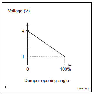
This sensor detects the position of the air mix control servo motor (air outlet damper) and sends the appropriate signals to the A/C amplifier. The position sensor is built in the air mix control servo motor. The position sensor resistance changes as the air mix control servo motor arm moves.
It outputs voltage (5 V) that is input to terminal 1 and terminal 3 via the
variable resistor, and then to the A/
C amplifier. The A/C amplifier determines the arm position based on the input
voltage from the position
sensor.
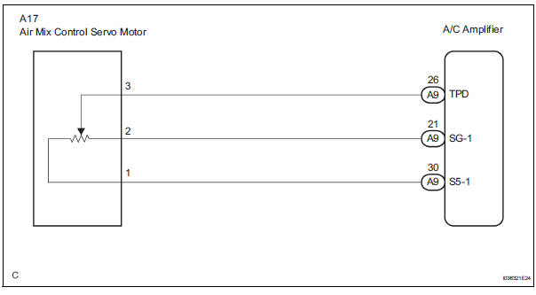
WIRING DIAGRAM
INSPECTION PROCEDURE
1 READ VALUE OF INTELLIGENT TESTER
(a) Connect the intelligent tester to the DLC3.
(b) Turn the ignition switch to the ON position and turn the intelligent tester main switch on.
(c) Select the items below in the DATA LIST, and read the display on the intelligent tester.
DATA LIST / AIR CONDITIONER 
OK: The display is as specified in the normal condition column.
Result 


2 INSPECT AIR MIX CONTROL SERVO MOTOR
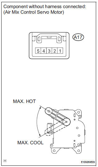
(a) Remove the air mix control servo motor.
(b) Disconnect the connector from the air mix control servo motor.
(c) Measure the resistance according to the value(s) in the table below.
Standard resistance 
(d) Measure the resistance according to the value(s) in the table below.
Standard resistance 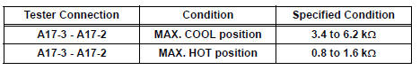
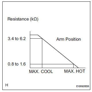
(e) As the air mix control servo motor moves from the COOL side to the HOT side, the resistance decreases gradually without interruption.


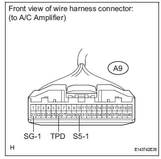
3 CHECK HARNESS AND CONNECTOR (AIR MIX CONTROL SERVO MOTOR - A/C AMPLIFIER)

(a) Disconnect the connector from the A/C amplifier.
(b) Measure the resistance according to the value(s) in the table below.
Standard resistance 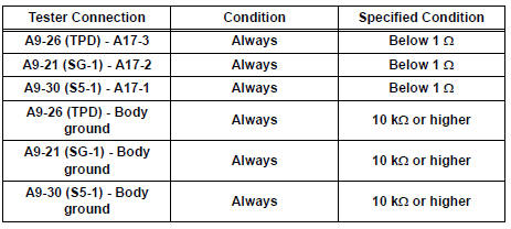

REPLACE A/C AMPLIFIER
 Air Outlet Damper Position Sensor Circuit
DESCRIPTION
This sensor detects the position of the air outlet control servo motor and
sends the appropriate signals to
the A/C amplifier. The position sensor is built in the air outlet contro ...
 Rear Air Mix Damper Position Sensor Circuit
DESCRIPTION
This sensor detects the position of the rear air mix control servo motor
(water valve servo motor) and
sends the appropriate signals to the A/C amplifier. The position sensor is bu ...
Other materials:
Road test
1. PROBLEM SYMPTOM CONFIRMATION
HINT:
The dynamic laser cruise control system has two cruise
control modes: the constant speed control mode and
vehicle-to-vehicle distance control mode.
The vehicle-to-vehicle distance control mode is
always selected when starting up the dynamic laser ...
Inspection
1. V
(a) Inspect VSV operation.
(1) Using an ohmmeter, measure the resistance
according to the value(s) in the table below.V
Standard resistance
If the result is not as specified, replace the
vsv.
(B) inspect the vsv for ground.
(1) Using an ohmmeter, measure the resistance
accordin ...
Reassembly
1. INSTALL PARKING BRAKE SWITCH ASSEMBLY
(a) Install the parking brake switch to the parking brake
pedal with the screw.
2. INSTALL PARKING BRAKE CABLE ASSEMBLY NO.1
(a) Connect the parking brake cable No. 1 to the
parking brake cable equalizer.
(b) Install the parking brake cable No. 1 with ...
