Toyota Sienna Service Manual: Reassembly
1. INSTALL CENTER SUPPORT BEARING ASSEMBLY NO.1

(a) Set the center support bearing assembly No. 1 (front) to the intermediate shaft, as shown in the illustration.
(b) Install a new washer to the intermediate shaft.
NOTICE: Be sure to install the bearing in the correct direction.

(c) Align the matchmarks on the front flange and shaft, and place the flange on the shaft.

(d) Using SST(s) to hold the front flange, press the center support bearing assembly No. 1 (front) into the position by tightening down with a new nut and plate washer.
SST 09330-00021 Torque: 181 N*m (1,850 kgf*cm, 134 ft.*lbf)
(e) Loosen the nut.
(f) Torque the nut again.
Torque: 69 N*m (700 kgf*cm, 51 ft.*lbf)
(g) Using a chisel and a hammer, stake the nut.
2. INSTALL CENTER SUPPORT BEARING ASSEMBLY NO.1

(a) Set the center support bearing assembly No. 1 (rear) on the shaft, as shown in the illustration.
(b) Install a new washer to the shaft.
NOTICE: Be sure to install the bearing in the correct direction.

(c) Align the matchmarks on the rear flange and shaft, and place the flange on the shaft.

(d) Using SST(s) to hold the front flange, press the center support bearing assembly No. 1 (rear) into the position by tightening down with a new nut and plate washer.
SST 09330-00021 Torque: 181 N*m (1,850 kgf*cm, 134 ft.*lbf)
(e) Loosen the nut.
(f) Torque the nut again.
Torque: 69 N*m (700 kgf*cm, 51 ft.*lbf)
(g) Using a chisel and a hammer, stake the nut.
3. INSTALL INTERMEDIATE SHAFT
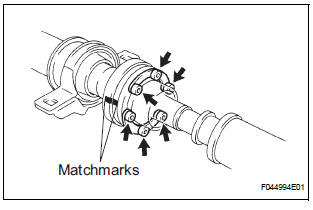
(a) Align the matchmarks on the intermediate shaft and rear propeller shaft assembly rear, then install the 2 washers and 6 bolts.
(b) Using a hexagon wrench (6 mm), loosely tighten the 6 bolts.
4. INSTALL PROPELLER SHAFT ASSEMBLY
(a) Align the matchmarks on the propeller shaft assembly flange and front flange, and connect the shaft with the 4 bolts, washers and nuts.
Torque: 74 N*m (750 kgf*cm, 54 ft.*lbf)

(b) Check that each joint of the propeller shaft is facing in the correct direction, as shown in the illustration below.

 Inspection
1. INSPECT SPIDER BEARING
(a) Check that the spider bearing moves smoothly by
turning the flange.
(b) Check for the looseness around the joint by strongly
moving the flange in the axial and ...
 Installation
1. INSTALL PROPELLER W/CENTER BEARING SHAFT ASSEMBLY
(a) Align the matchmarks on the propeller shaft
assembly rear flange and differential companion
flange, and connect the shaft with the 4 bol ...
Other materials:
Illumination Circuit
DESCRIPTION
The Multiplex network body ECU controls illumination light as shown in the
chart below.
Room light assembly (Interior light, luggage component light) and
courtesy light with DOOR position
Map light assembly (Personal light)
Transponder key amplifier (Ignition ke ...
Installation
1. INSTALL ROOF HEADLINING ASSEMBLY
w/ sliding roof:
Install the roof headlining with the 5 clips.
w/o sliding roof:
Install the roof headlining with the 3 clips.
NOTICE:
In order to prevent the roof headlining from
becoming bent, work must be performed by 2 or
more persons when ...
Initialization
1. RESET
When the back door lock is replaced:
The power back door ECU cannot receive a switch
signal from the lock. This may cause the power
back door system to enter fail-safe mode and DTC
B2215 to set, and also make the system disabled.
When the lock is replaced, be sure to perform t ...
