Toyota Sienna Service Manual: Adjustment
HINT: On the RH side, use the same procedures as on the LH side.
1. INSPECT SLIDE DOOR PANEL SUB-ASSEMBLY LH
- Check that the clearance is within the standard range.
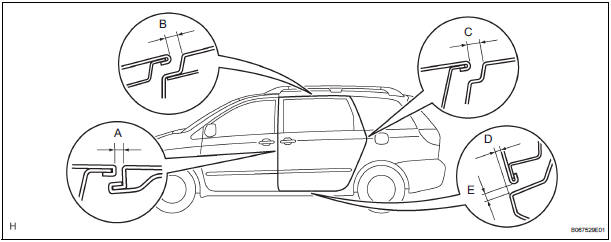
Standard

2. ADJUST SLIDE DOOR PANEL SUB-ASSEMBLY LH

- Using the SST, horizontally and vertically adjust the
door by loosening the hinge center bolts.
SST 09812-00010, 09812-00020
- Tighten the hinge center bolts after the adjustment.
Torque: 31 N*m (306 kgf*cm, 23 ft.*lbf)

- Vertically adjust the front side of the door by loosening the roller lower bolts.
- Tighten the roller lower bolts after the adjustment.
Torque: 31 N*m (306 kgf*cm, 23 ft.*lbf)

- Horizontally adjust the front lower side of the door by loosening the roller lower bolts.
- Tighten the roller lower bolts after the adjustment.
Torque: 31 N*m (306 kgf*cm, 23 ft.*lbf)

- Horizontally adjust the front upper side of the door by loosening the roller upper bolts.
- Tighten the roller lower bolts after the adjustment.
Torque: 8.5 N*m (82 kgf*cm, 73 in.*lbf)

- Adjust the position the door lock striker by slightly loosening the striker mounting screws and hitting the striker with a plastic-faced hammer.
- Tighten the striker mounting screws after the
adjustment.
Torque: 23 N*m (235 kgf*cm, 17 ft.*lbf)
- Adjust the position the front lock striker by slightly loosening the striker mounting screws and hitting the striker with a plastic-faced hammer.
- Tighten the striker mounting screws after the
adjustment.
Torque: 23 N*m (235 kgf*cm, 17 ft.*lbf)
- Adjust the position of the down stopper by moving the male stopper, so that the male stopper can enter smoothly.
- Tighten the female stopper mounting bolts after the
adjustment.
Torque: 5.5 N*m (58 kgf*cm, 49 in.*lbf)
 Disassembly
1. REMOVE REAR DOOR WINDOW FRAME MOULDING
REAR LH (See page ET-31)
2. REMOVE REAR DOOR WINDOW FRAME MOULDING
SUB-ASSEMBLY LH (See page ET-32)
3. REMOVE SLIDE DOOR WINDOW GARNISH LH
Fully o ...
 Reassembly
1. INSTALL POWER SLIDE DOOR TOUCH SENSOR LH
Install the touch sensor with the 4 screws.
Connect the connector.
Fix the wire harness inside the door panel with the
clip.
2. INSTALL REA ...
Other materials:
On-vehicle inspection
1. CHECK VVT SENSOR OUTPUT VOLTAGE
Turn the ignition switch to the ON position.
Check the voltage between the specified terminal
and body ground.
Standard voltage
While turning the crankshaft pulley by hand,
measure the voltage between each terminal. Check
that the voltage ...
Mass or Volume Air Flow Circuit Range / Performance
Problem
DTC P0101 Mass or Volume Air Flow Circuit Range / Performance
Problem
DESCRIPTION
Refer to DTC P0100
DTC No.
DTC Detection Condition
Trouble Area
P0101
High voltage:
Conditions (a), (b) and (c) continue for more than
10 seconds (2 trip de ...
Inspection procedure
1 BASIC INSPECTION
Conditions necessary for the power slide door to open:
Power slide door main switch is in the ON position
(switch free: orange paint on the top of the switch
appears).
Slide door is unlocked (door lock position switch is
in the ON position when the slide do ...