Toyota Sienna Service Manual: Air Mix Damper Control Servo Motor Circuit (Passenger Side)
DESCRIPTION
The air mix control servo motor (air mix damper servo sub-assembly) is controlled by the A/C amplifier.
The air mix control servo motor moves the air mix damper by rotating (normal, reverse) with electrical power from the A/C amplifier.
This adjusts the mix ratio of the air that passes through the evaporator and heater core and controls the air flow temperature. Air flow temperature changes when the air mix damper is moved to the target point.
The target point can be detected by the air mix damper position sensor.
WIRING DIAGRAM

INSPECTION PROCEDURE
1 READ VALUE OF INTELLIGENT TESTER
(a) Connect the intelligent tester to the DLC3.
(b) Turn the ignition switch to the ON position and turn the intelligent tester main switch on.
(c) Select the items below in the DATA LIST, and read the display on the intelligent tester.
DATA LIST / AIR CONDITIONER 
OK: When the target position is "MAX. COOL" (-5%), the actual opening angle is 19.0% or less.
When the target position is "MAX. HOT" (105%), the actual opening angle is 81.0% or more.
Result 


2 PERFORM ACTIVE TEST BY INTELLIGENT TESTER
(a) Connect the intelligent tester to the DLC3.
(b) Turn the ignition switch to the ON position and turn the intelligent tester main switch on.
(c) Select the item below in the ACTIVE TEST and then check the air flow temperature by hand.
ACTIVE TEST / AIR CONDITIONER 
OK: When the lever is moved to the "MAX. HOT" side, warm air comes out.
When the lever is moved to the "MAX. COOL" side, cool air comes out.
Result 


3 PERFORM ACTUATOR CHECK
(a) Enter the actuator check mode (See page AC-15).
(b) Press the DEF switch and change to the step operation.
(c) Check the air flow temperature by hand.

OK: Air flow temperature changes in accordance with each display code.
Result 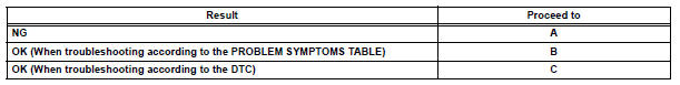


4 INSPECT AIR MIX CONTROL SERVO MOTOR

(a) Remove the air mix control servo motor.
(b) Disconnect the connector from the air mix control servo motor.
(c) Connect the positive (+) lead from the battery to terminal 5 and the negative (-) lead to terminal 4, then check that the lever turns to the "MAX. HOT" position smoothly.
OK: Lever turns to "MAX. HOT" position smoothly.
(d) Connect the positive (+) lead from the battery to terminal 4 and the negative (-) lead to terminal 5, then check that the lever turns to the "MAX. COOL" position smoothly.
OK: Lever turns to "MAX. COOL" position smoothly.


5 CHECK HARNESS AND CONNECTOR (AIR MIX CONTROL SERVO MOTOR - A/C AMPLIFIER)

(a) Disconnect the connector from the A/C amplifier.

(b) Measure the resistance according to the value(s) in the table below.
Standard resistance 


REPLACE A/C AMPLIFIER
 Rear Air Outlet Damper Position Sensor Circuit
DESCRIPTION
This sensor detects the position of the rear air outlet control servo motor
and sends the appropriate
signals to the A/C amplifier. The position sensor is built in the rear air
o ...
 Air Inlet Damper Control Servo Motor Circuit
DESCRIPTION
The air inlet control servo motor is controlled by the A/C amplifier and
moved to the desired position.
The air inlet control servo motor switches the air inlet mode by rotating
(n ...
Other materials:
Data list / active test
1. DATA LIST
HINT:
Using the intelligent tester to read the DATA LIST allows
the values or states of switches, sensors, actuators and
other items to be read without removing any parts. This
non-intrusive inspection can be very useful because
intermittent conditions or signals may be discovered ...
Removal
1. REMOVE ENGINE ASSEMBLY WITH TRANSAXLE
HINT:
See page EM-26
2. SECURE ENGINE (See page EM-37)
3. REMOVE GENERATOR ASSEMBLY (See page CH-17)
4. REMOVE COMPRESSOR AND MAGNETIC CLUTCH
(See page AC-227)
5. REMOVE NO. 1 ENGINE FRONT MOUNTING
BRACKET LH (See page EM-42)
6. REMOVE NO. 2 IDLER PU ...
Diagnostic trouble code chart
If a trouble code is displayed during the DTC check, check
the circuit listed for that code. For details of each code, turn
the page mentioned below the "DTC No" in the DTC chart.
the "DTC No" in the DTC chart.
1. TRANSPONDER KEY ECU DIAGNOSTIC TROUBLE
CODE CHART
TRANSPON ...