Toyota Sienna Service Manual: Rear Air Outlet Damper Position Sensor Circuit
DESCRIPTION

This sensor detects the position of the rear air outlet control servo motor and sends the appropriate signals to the A/C amplifier. The position sensor is built in the rear air outlet control servo motor.
The position sensor's resistance changes as the rear air outlet control servo motor arm moves.
It outputs voltage (5 V) that is input to terminal 2 and terminal 3 via the variable resister, and then to the A/ C amplifier.
The A/C amplifier determines the arm position based on the input voltage from
the position sensor.
WIRING DIAGRAM

INSPECTION PROCEDURE
1 READ VALUE OF INTELLIGENT TESTER
(a) Connect the intelligent tester to the DLC3.
(b) Turn the ignition switch to the ON position and turn the intelligent tester main switch on.
(c) Select the items below in the DATA LIST, and read the display on the intelligent tester.
DATA LIST / AIR CONDITIONER 
OK: The display is as specified in the normal condition column.
Result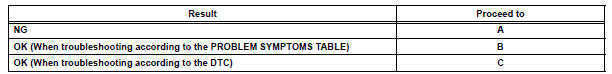


2 INSPECT REAR AIR OUTLET CONTROL SERVO MOTOR

(a) Remove the rear air outlet control servo motor.
(b) Disconnect the connector from the rear air outlet control servo motor.
(c) Measure the resistance according to the value(s) in the table below.
Standard resistance
(d) Measure the resistance according to the value(s) in the table below.
Standard resistance 

(e) As the rear air outlet control servo motor moves from FACE to FOOT, the resistance decreases gradually without interruption.


3 CHECK HARNESS AND CONNECTOR (REAR AIR OUTLET CONTROL SERVO MOTOR - A/C AMPLIFIER)

(a) Disconnect the connector from the A/C amplifier.

(b) Measure the resistance according to the value(s) in the table below.
Standard resistance 


REPLACE A/C AMPLIFIER
 Rear Air Mix Damper Position Sensor Circuit
DESCRIPTION
This sensor detects the position of the rear air mix control servo motor
(water valve servo motor) and
sends the appropriate signals to the A/C amplifier. The position sensor is bu ...
 Air Mix Damper Control Servo Motor Circuit (Passenger Side)
DESCRIPTION
The air mix control servo motor (air mix damper servo sub-assembly) is
controlled by the A/C amplifier.
The air mix control servo motor moves the air mix damper by rotating (normal, ...
Other materials:
Front No. 2 speaker
COMPONENTS
ON-VEHICLE INSPECTION
1. INSPECT FRONT NO.2 SPEAKER
HINT:
Remove interior parts so that the front No.2 speaker can
be seen.
Check the speaker installation.
OK:
The speaker is securely installed.
If the result is not as specified, reinstall the front
No.2 speak ...
Power Seat Motor Circuit
DESCRIPTION
When the power seat control switch is operated, a command signal is sent to
the position control ECU
and switch assembly (power seat control switch and ECU). The front power seat
switch then controls the
appropriate seat motor as needed. This memory system does not use a seat
po ...
Short to B+ in Front Pretensioner Squib LH Circuit
DTC B0138/72 Short to B+ in Front Pretensioner Squib LH Circuit
DESCRIPTION
The front pretensioner squib LH circuit consists of the center airbag sensor
assembly and the front seat
outer belt assembly LH.
This circuit instructs the SRS to deploy when deployment conditions are met.
DTC B01 ...