Toyota Sienna Service Manual: CAN Bus Line
DESCRIPTION
When any DTC for the CAN communication system is output, first measure the resistance between the terminals of the DLC3 to specify the trouble area, and check that there is no short in the CAN main wire, between the main wire, and +B or GND.
WIRING DIAGRAM


INSPECTION PROCEDURE
NOTICE:
- Turn the ignition switch off before measuring the resistances of CAN bus main wires and CAN bus branch wires.
- After the ignition switch is turned off, check that the key reminder warning system and light reminder warning system are not in operation.
- Before measuring the resistance, leave the vehicle as is for at least 1 minute and do not operate the ignition switch, any other switches, or the doors. If any doors need to be opened in order to check connectors, open the doors and leave them open.
HINT: Operating the ignition switch, any switches, or any doors triggers related ECU and sensor communication with the CAN. This communication will cause the resistance value to change.
1 CHECK CAN BUS WIRE (MAIN WIRE FOR DISCONNECTION, CAN BUS LINES FOR SHORT CIRCUIT)

- Turn the ignition switch off.
- Measure the resistance according to the value(s) in the table below.
Standard resistance

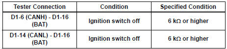
2 CHECK FOR SHORT TO B+ IN CAN BUS WIRE

- Measure the resistance according to the value(s) in the table below.
Standard resistance
3 CHECK FOR SHORT TO GND IN CAN BUS WIRE

- Measure the resistance according to the value(s) in the table below.
Standard resistance

GO TO HOW TO PROCEED WITH TROUBLESHOOTING
 ECM Communication Stop Mode
DESCRIPTION
Detection Item
Symptom
Trouble Area
ECM Communication Stop
Mode
"Engine" is not displayed on the "Communication
Bus Che ...
 Open in CAN Main Bus Line
DESCRIPTION
There may be an open circuit in the CAN main bus wire and/or the DLC3 branch
wire when the resistance
between terminals 6 (CANH) and 14 (CANL) of the DLC3 is 69 Ω or higher.
...
Other materials:
TRAC OFF Indicator Light Remains ON
DESCRIPTION
The skid control ECU is connected to the combination meter via CAN and
multiplex communications.
When the traction OFF switch is turned on, the TRAC OFF indicator light will
come on (for 2WD model).
WIRING DIAGRAM
INSPECTION PROCEDURE
NOTICE:
When replacing the brake actu ...
Intake Air Temperature Sensor Gradient Too
High
DTC P0111 Intake Air Temperature Sensor Gradient Too
High
DESCRIPTION
The Intake Air Temperature (IAT) sensor, mounted on the Mass Air Flow (MAF)
meter, monitors the IAT.
The IAT sensor has a built-in thermistor with a resistance that varies according
to the temperature of the
intake ...
Removal
1. Remove front wheel
2. Remove front wiper arm head cap
Hint:
(see page ww-3)
3. Remove fr wiper arm rh
HINT:
(See page WW-3)
4. Remove fr wiper arm lh
HINT:
(See page WW-3)
5. Remove cowl top ventilator louver subassembly
Hint:
(see page ww-3)
6. Remove windshield wiper motor & li ...