Toyota Sienna Service Manual: Check for short circuit
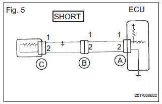
(a) If the wire harness is ground shorted (Fig. 5), locate the section by conducting a resistance check with the body ground (below).

(b) Check the resistance with the body ground.
(1) Disconnect connectors A and C and measure the resistance.
Standard resistance (Fig. 6)

HINT:
Measure the resistance while lightly shaking the wire harness vertically and horizontally. If your results match the examples above, an open circuit exists between terminal 1 of connector A and terminal 1 of connector C.
(2) Disconnect connector B and measure the resistance.

Standard resistance (Fig. 7)
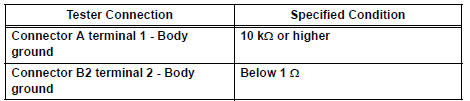
If the results match the examples above, a short circuit exists between terminal 1 of connector B2 and terminal 1 of connector C.
 Check for open circuit
(a) For an open circuit in the wire harness in Fig. 1, the resistance or
voltage, as described below.
(b) Check the resistance.
Check the resistance
Standard resistance (Fig. 2)
...
 Check and replace ecu
NOTICE: • The connector should not be disconnected from
the ECU. Perform the inspection from the
backside of the connector on the wire harness
side.
• When no measuring condition is s ...
Other materials:
How to proceed with
troubleshooting
HINT:
The intelligent tester can be used in steps 2, 3, 4, 6 and 9.
1 VEHICLE BROUGHT TO WORKSHOP
2 CONNECT INTELLIGENT TESTER TO DLC3
HINT:
If the display indicates a communication fault in the tester,
inspect the DLC3.
3 CHECK DTC AND FREEZE FRAME DATA
Check for DTC(s) and freeze frame ...
Disassembly
1. REMOVE AIR REFINER ELEMENT
(a) Release the 2 claw fittings and remove the air filter
sub-assembly.
(b) Remove the air refiner element from the air filter
cover plate.
2. REMOVE COOLING UNIT DAMPER SERVO SUBASSEMBLY
(a) Remove the 3 screws and the cooling unit damper
servo sub-a ...
Adjustment
1. INSPECT SHIFT LEVER POSITION
(a) When shifting from P to R position only with ignition
switch ON and brake pedal, make sure that the
shifting lever moves smoothly and can be
moderately operated.
(b) When starting engine, make sure that the vehicle
moves forward when shifting from N to D p ...