Toyota Sienna Service Manual: Reassembly
1. INSTALL IGNITION OR STARTER SWITCH ASSEMBLY
(a) Install the ignition or starter switch assembly to the steering column bracket assembly UPR with the 2 screws.
2. INSTALL KEY INTER LOCK SOLENOID
(a) Install the solenoid to the steering column bracket assembly with the 2 screws.
3. INSTALL UN-LOCK WARNING SWITCH ASSEMBLY

(a) Install the un-lock warning switch assembly.
(b) Connect terminals 1 and 2 of the un-lock warning switch assembly connector.
(c) Connect the un-lock warning switch assembly connector to the ignition or starter switch assembly.
4. INSTALL IGNITION SWITCH LOCK CYLINDER ASSEMBLY
(a) Make sure that the ignition switch lock cylinder assembly is in the ACC position.
(b) Install the ignition switch lock cylinder assembly.
5. INSTALL STEERING LOCK OPERATION
(a) Check that the steering lock mechanism is activated when removing the key.
(b) Check that the steering lock mechanism is deactivated when inserting the key and turning it to the ACC position
6. INSTALL STEERING COLUMN BRACKET ASSEMBLY UPPER

(a) Temporarily install the steering column upper w/ switch bracket assembly and steering column upper clamp with 2 new tapered-head bolts.
(b) Tighten the 2 tapered-head bolts until the bolt heads break off.
7. INSTALL KEY CYLINDER LIGHT ASSEMBLY (w/o Engine Immobiliser System)
8. INSTALL TRANSPONDER KEY AMPLIFIER (w/ Engine Immobiliser System)

(a) Align the transponder key amplifier with the installation position of the upper bracket with the amplifier inclined.
(b) Push the transponder key amplifier up and connect it to the upper bracket.
NOTICE: Take care not to push the amplifier up with excessive force to prevent it from being damaged.
9. INSTALL STEERING INTERMEDIATE SHAFT ASSEMBLY
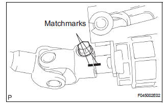
(a) Align the matchmarks on the steering intermediate shaft assembly and main shaft.
(b) Temporarily install the steering intermediate shaft assembly with the bolt.
Torque: 36 N*m (370 kgf*cm, 27 ft.*lbf)
 Disassembly
1. REMOVE STEERING INTERMEDIATE SHAFT ASSEMBLY
(a) Align the matchmarks on the steering intermediate
shaft assembly and main shaft.
(b) Remove the bolt and steering intermediate shaft
assemb ...
 Installation
1. INSTALL STEERING COLUMN ASSEMBLY
(a) Install the steering column assembly with the 3
bolts.
Torque: 25 N*m (255 kgf*cm, 18 ft.*lbf)
(b) Connect the connectors.
(c) Connect the wire har ...
Other materials:
Brake Warning Light Remains ON
DESCRIPTION
The BRAKE warning light comes on when the brake fluid is insufficient, the
parking brake is applied or the
EBD is defective.
WIRING DIAGRAM
INSPECTION PROCEDURE
HINT:
When releasing the parking brake, move the shift lever into the P position in an
AT vehicle, and choke in
...
ECM Communication Circuit Malfunction
DTC C1203/53 ECM Communication Circuit Malfunction
DESCRIPTION
The circuit is used to send TRAC and VSC control information from the skid
control ECU to the ECM, and
engine control information from the ECM to the skid control ECU through the CAN
communication
system.
INSPECTION PROCEDURE
1 ...
Map Disc Read Error
DTC 58-42 Map Disc Read Error
DTC 80-42 Map Disc Read Error
DESCRIPTION
DTC No.
DTC Detection Condition
Trouble Area
58-42
Player error
Scratches or dirt on the disc
Access to an invalid address due to software error
...