Toyota Sienna Service Manual: Disassembly
1. REMOVE RETURN TUBE NO.2

(a) Using SST, remove the return tube No. 2.
SST 09023-12701
2. REMOVE STEERING LEFT TURN PRESSURE TUBE

(a) Using SST, remove the left turn pressure tube.
SST 09023-38201 (b) Remove the 2 O-rings from the left turn pressure tube.
3. REMOVE STEERING RIGHT TURN PRESSURE TUBE SST 09023-38201
HINT: Perform the same procedure on the other side.
4. FIX RACK & PINION POWER STEERING GEAR ASSEMBLY

(a) Using SST, secure the power steering gear assembly.
SST 09612-00012
HINT: Tape the SST before use.
5. REMOVE TIE ROD ASSEMBLY LH
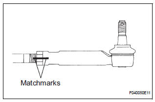
(a) Place matchmarks on the tie rod assembly and rack end sub-assembly.
(b) Loosen the lock nut, and remove the tie rod assembly and lock nut.
6. REMOVE TIE ROD ASSEMBLY RH
HINT: Perform the same procedure on the other side.
7. REMOVE STEERING RACK BOOT CLIP
(a) Remove the 2 rack boot clips.
8. REMOVE STEERING RACK BOOT NO.2 CLAMP
(a) Using pliers, remove the rack boot No. 2 clamp.
NOTICE: Be careful not to damage the steering rack boot No. 2.
9. REMOVE STEERING RACK BOOT NO.1 CLAMP
HINT: Perform the same procedure on the other side.
10. REMOVE STEERING RACK BOOT NO.2
11. REMOVE STEERING RACK BOOT NO.1
12. REMOVE STEERING RACK END SUB-ASSEMBLY

(a) Using a screwdriver and a hammer, unstake the claw washer.
NOTICE: Avoid any impact to the power steering rack.

(b) Using 2 SST, remove the 2 steering rack end subassembly and 2 claw washers.
SST 09922-10010
NOTICE:
- Use SST 09922-10010 in the direction shown in the illustration.
- Securely hold the power steering rack end with a SST.
13. REMOVE RACK GUIDE

(a) Using SST, remove the rack guide spring cap nut.
SST 09922-10010
NOTICE: Use SST 09922-10010in the direction shown in the illustration.

(b) Using SST, remove the rack guide spring cap.
SST 09631-10021 (c) Remove the compression spring and the rack guide.
14. REMOVE POWER STEERING CONTROL VALVE

(a) Using a socket wrench (27 mm), remove the rack housing cap.

(b) Using SST, hold the control valve and remove the nut.
SST 09616-00011

(c) Wind vinyl tape around the serrated part of the control valve.
(d) Remove the dust cover from the control valve housing.

(e) Remove the 2 bolts and the control valve w/ control valve housing.
(f) Remove the gasket.

(g) To prevent oil seal lip damage, wind vinyl tape around the serrated part of the control valve.
(h) Using a plastic hammer, remove the control valve w/ oil seal from the control valve housing.
(i) Remove the oil seal from the control valve.

(j) Using a screwdriver, remove the 4 control valve rings.
NOTICE: Be careful not to damage the grooves for the control valve rings.
15. REMOVE POWER STEERING CONTROL VALVE UPPER OIL SEAL

(a) Using SST and a press, remove the control valve upper bearing and control valve upper oil seal from the control valve housing.
SST 09950-70010 (09951-07150), 09950-60010 (09951-00250)
16. REMOVE CYLINDER END STOPPER

(a) Using a screwdriver and a hammer, turn the cylinder end stopper clockwise until the wire end is visible through the service hole.
(b) Using a screwdriver and a hammer, turn the cylinder end stopper counterclockwise, and remove the wire and cylinder end stopper
17. REMOVE POWER STEERING RACK
18. REMOVE POWER STEERING RACK BUSH

(a) Remove the rack bush from the power steering rack.
(b) Using SST, remove the rack bush oil seal.
SST 09527-21011, 09612-24014 (09613-22011) (c) Using a screwdriver, remove the O-ring from the rack bush.
19. REMOVE POWER STEERING CYLINDER TUBE OIL SEAL

(a) Using SST and a press, remove the cylinder tube oil seal.
SST 09950-70010 (09951-07360), 09950-60010 (09951-00290)
20. REMOVE RACK STEERING PISTON RING

(a) Using a screwdriver, remove the rack steering piston ring and O-ring.
NOTICE: Be careful not to damage the grooves for rack steering piston ring.
 Removal
NOTICE:
When installing, coat the parts indicated by the arrows
with power steering fluid or molybdenum disulfide
lithium base grease (See page PS-21).
1. INSPECT CENTER FRONT WHEEL
2. REMOVE FRO ...
 Inspection
1. INSPECT POWER STEERING RACK
(a) Using a dial indicator, check the power steering rack
for runout and for teeth wear and damage.
Maximum runout:
0.3 mm (0.012 in.)
If necessary, replace t ...
Other materials:
Dtc check / clear
1. DTC CHECK/CLEAR (WHEN USING SST CHECK WIRE):
(a) DTC check
(1) Using SST, connect terminals TC and CG of the
DLC3.
SST 09843-18040
(2) Turn the ignition switch to the ON position.
(3) Read the DTCs from the ABS warning light on
the combination meter.
HINT:
If no code appears, inspe ...
DSP Error
DTC 44-78 DSP Error
DESCRIPTION
DTC No.
DTC Detecting Condition
Trouble Area
44-78
An error occurs during the decode process (MP3/
WMA).
-
INSPECTION PROCEDURE
HINT:
After the inspection is completed, clear the DTCs.
NOTICE:
Thi ...
Scratched / Reversed Disc
DTC 62-46 Scratched / Reversed Disc
DTC 63-46 Scratched / Reversed Disc
DESCRIPTION
DTC No.
DTC Detecting Condition
Trouble Area
62-46
Scratches or dirt is found on CD surface or CD is set
upside down.
CD
Radio receiver
...