Toyota Sienna Service Manual: Removal
NOTICE: When installing, coat the parts indicated by the arrows with power steering fluid or molybdenum disulfide lithium base grease (See page PS-21).
1. INSPECT CENTER FRONT WHEEL
2. REMOVE FRONT WHEEL
3. SEPARATE TIE ROD ASSEMBLY LH SST 09628-62011
4. SEPARATE TIE ROD ASSEMBLY RH SST 09628-62011
HINT: Perform the same procedure on the other side.
5. SEPARATE STEERING INTERMEDIATE SHAFT ASSEMBLY
(a) Fix the steering wheel with the seat belt.
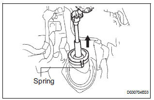
(b) Release the 3 springs and separate the dust cover.
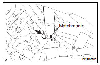
(c) Place matchmarks on the intermediate shaft assembly and power steering gear assembly.
(d) Remove the bolt and separate the intermediate shaft assembly.
6. SEPARATE FRONT STABILIZER LINK ASSEMBLY LH
7. SEPARATE FRONT STABILIZER LINK ASSEMBLY RH
HINT: Perform the same procedure on the other side.
8. REMOVE FRONT STABILIZER BRACKET NO.1 LH
(a) Remove the 2 bolts and remove the stabilizer bracket No. 1.
9. REMOVE FRONT STABILIZER BRACKET NO.1 RH
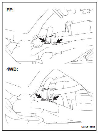
HINT: Perform the same procedure on the other side.
10. DISCONNECT PRESSURE FEED TUBE ASSEMBLY

(a) Remove the clip and disconnect the return tube assembly from the power steering gear assembly.

(b) Using SST, disconnect the pressure feed tube assembly from the power steering gear assembly.
SST 09023-12701
(c) Remove the bolt and separate the tube clamp.

(d) Remove the nut and separate the tube clamp.
11. REMOVE RACK & PINION POWER STEERING GEAR ASSEMBLY

(a) Remove the 2 bolts, nuts and the power steering gear assembly.
NOTICE: Do not damage the 2 pressure tubes.
 Rack and pinion power steering gear
COMPONENTS
...
 Disassembly
1. REMOVE RETURN TUBE NO.2
(a) Using SST, remove the return tube No. 2.
SST 09023-12701
2. REMOVE STEERING LEFT TURN PRESSURE TUBE
(a) Using SST, remove the left turn pressure tube.
S ...
Other materials:
SFR Solenoid Circuit
DESCRIPTION
The solenoid comes on when signals are received from the ECU and controls the
pressure acting on the
wheel cylinders, thus controlling brake force.
WIRING DIAGRAM
INSPECTION PROCEDURE
1 RECONFIRM DTC
HINT:
These codes are detected when a problem is identified in the
...
Removal
1. REMOVE BACK DOOR CENTER GARNISH (See page
ET-18)
2. REMOVE POWER BACK DOOR ROD (See page ED-
220)
3. REMOVE BACK DOOR LH SIDE GARNISH
4. REMOVE BACK DOOR RH SIDE GARNISH
5. REMOVE BACK DOOR PULL STRAP (See page ED-
221)
6. REMOVE BACK DOOR TRIM BOARD ASSEMBLY
7. REMOVE LH BACK-UP LIGH ...
Short in Front Passenger Side Squib 2nd Step
Circuit
DTC B1185/57 Short in Front Passenger Side Squib 2nd Step
Circuit
DESCRIPTION
The front passenger side squib 2nd step circuit consists of the center airbag
sensor assembly and the
front passenger airbag assembly.
The circuit instructs the SRS to deploy when deployment conditions are met.
...