Toyota Sienna Service Manual: Disassembly
1. REMOVE BLOWER ASSEMBLY

(a) Remove the 2 screws and the blower assembly.
2. REMOVE MODE DAMPER SERVO SUB-ASSEMBLY

(a) Remove the 3 screws and the mode damper servo sub-assembly.
3. REMOVE AIRMIX DAMPER SERVO SUB-ASSEMBLY

(a) Remove the 3 screws and the airmix damper servo sub-assembly.
4. REMOVE NO. 2 AIRMIX DAMPER SERVO SUBASSEMBLY (for Automatic Air Conditioning System)
(a) Remove the 3 screws and the No. 2 airmix damper servo sub-assembly.
5. REMOVE NO. 1 HEATER CLAMP
(a) Release the 4 claw fittings and remove the No. 1 heater clamp.
6. REMOVE NO. 3 AIR CONDITIONING RADIATOR BRACKET

(a) Remove the screw and the No. 3 air conditioning radiator bracket.
7. REMOVE HEATER RADIATOR UNIT SUB-ASSEMBLY

(a) Remove the heater radiator unit sub-assembly from the air conditioning radiator assembly.
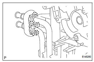
8. REMOVE AIR CONDITIONING TUBE ASSEMBLY

(a) Using a hexagon wrench 4.0 mm (0.15 in.), remove the 2 hexagon bolts and the air conditioning tube assembly.
(b) Remove the 2 O-rings from the air conditioning tube assembly.
9. REMOVE COOLER EXPANSION VALVE

(a) Remove the cooler expansion valve from the No. 1 cooler evaporator sub-assembly.

(b) Remove the 2 O-rings from the No. 1 cooler evaporator sub-assembly.
10. REMOVE NO. 2 AIR CONDITIONING RADIATOR BRACKET

(a) Remove the 2 screws and the No. 2 air conditioning radiator bracket.
11. REMOVE NO. 1 AIR CONDITIONING RADIATOR BRACKET

(a) Remove the 3 screws and the No .1 air conditioning radiator bracket.
12. REMOVE NO. 4 AIR CONDITIONING RADIATOR BRACKET

(a) Remove the No. 4 air conditioning radiator bracket.
13. REMOVE NO. 1 AIR DUCT

(a) Release the 4 claw fittings and remove the No. 1 air duct.
14. REMOVE NO. 1 COOLER THERMISTOR

(a) Disengage the clamp.
(b) Remove the 2 screws.

(c) Remove the 11 screws.

(d) Remove the No. 1 cooler thermistor.
 Removal
1. RECOVER REFRIGERANT FROM REFRIGERATION
SYSTEM (See page AC-172)
2. REMOVE FRONT WIPER ARM HEAD CAP (See page
WW-4)
3. REMOVE FRONT WIPER ARM RH (See page WW-4)
4. REMOVE FRONT WIPER ARM LH (Se ...
 Reassembly
1. INSTALL NO. 1 COOLER THERMISTOR
(a) Install the No. 1 cooler thermistor as shown in the
illustration.
NOTICE:
Be sure to insert the thermistor only once
because reinserting it will no ...
Other materials:
Power Windows do not Operate at All
DESCRIPTION
If all of the door windows do not operate, no power may be supplied to the
power window master switch or
the power window master switch itself may have a malfunction.
WIRING DIAGRAM
INSPECTION PROCEDURE
1 INSPECT FUSE (PWR, ECU-IG, AM1)
Remove the fuses from the driver sid ...
System Voltage
MONITOR DESCRIPTION
The battery supplies electricity to the ECM even when the ignition switch is
off. This power allows the
ECM to store data such as DTC history, freeze frame data and fuel trim values.
If the battery voltage falls
below a minimum level, these memories are cleared and the ...
Check mode procedure
HINT:
Intelligent tester only:
Compared to normal mode, check mode is more sensitive to
malfunctions. Therefore, check mode can detect the
malfunctions that cannot be detected by normal mode.
NOTICE:All the stored DTCs and freeze frame data are
erased if:
1) the ECM is changed fro ...