Toyota Sienna Service Manual: Reassembly
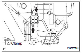
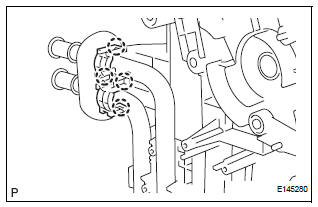
1. INSTALL NO. 1 COOLER THERMISTOR

(a) Install the No. 1 cooler thermistor as shown in the
illustration. 
NOTICE:
- Be sure to insert the thermistor only once because reinserting it will not allow it to be firmly secured.
- When reusing the evaporator, insert the thermistor one row next to the one that had been used previously (X in the illustration).
- After inserting the thermistor, do not apply excessive force to the wire.
- Directly insert the thermistor until the edge of plastic case "a" comes into contact with evaporator "b".
(b) Install the 11 screws.
(c) Install the 2 screws.
(d) Engage the clamp.
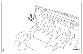
2. INSTALL NO. 1 AIR DUCT

(a) Engage the 4 claws and install the No. 1 air duct.
3. INSTALL NO. 4 AIR CONDITIONING RADIATOR BRACKET
4. INSTALL NO. 1 AIR CONDITIONING RADIATOR BRACKET

(a) Install the No. 1 air conditioning radiator bracket with the 3 screws.
5. INSTALL NO. 2 AIR CONDITIONING RADIATOR BRACKET

(a) Install the No. 2 air conditioning radiator bracket with the 2 screws.
6. INSTALL COOLER EXPANSION VALVE
(a) Sufficiently apply compressor oil to 2 new O-rings and the fitting surface of the No. 1 cooler evaporator sub-assembly.
Compressor oil: ND-OIL 8 or equivalent

(b) Install the cooler expansion valve to the No. 1 cooler evaporator sub-assembly.
7. INSTALL AIR CONDITIONING TUBE ASSEMBLY
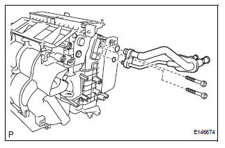
(a) Sufficiently apply compressor oil to 2 new O-rings and the fitting surface of the air conditioning tube assembly.
Compressor oil: ND-OIL 8 or equivalent
(b) Install the 2 O-rings on the air conditioning tube assembly.
(c) Using a hexagon wrench 4.0 mm (0.15 in.), install the air conditioning tube assembly with the 2 hexagon bolts.
Torque: 3.5 N*m (35 kgf*cm, 30 in.*lbf)
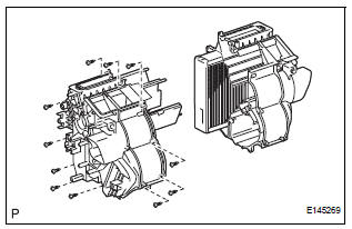
8. INSTALL HEATER RADIATOR UNIT SUB-ASSEMBLY
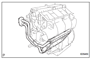
(a) Install the heater radiator unit sub-assembly to the air conditioning radiator assembly.
9. INSTALL NO. 3 AIR CONDITIONING RADIATOR BRACKET
(a) Install the No. 3 air conditioning radiator bracket with the screw.
10. INSTALL NO. 1 HEATER CLAMP
(a) Engage the 4 claws and install the No. 1 heater clamp.
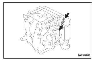
11. INSTALL NO. 2 AIRMIX DAMPER SERVO SUBASSEMBLY (for Automatic Air Conditioning System)
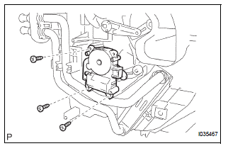
(a) Install the No. 2 airmix damper servo sub-assembly with the 3 screws.
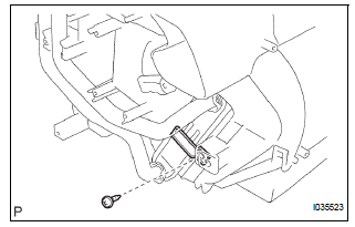
12. INSTALL AIRMIX DAMPER SERVO SUB-ASSEMBLY

(a) Install the airmix damper servo sub-assembly with the 3 screws.
13. INSTALL MODE DAMPER SERVO SUB-ASSEMBLY

(a) Install the mode damper servo sub-assembly with the 3 screws.
14. INSTALL BLOWER ASSEMBLY
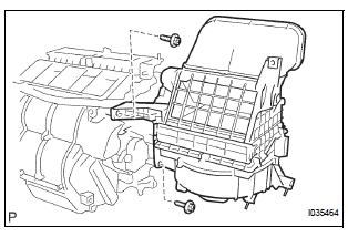
(a) Install the blower assembly with the 2 screws.
 Disassembly
1. REMOVE BLOWER ASSEMBLY
(a) Remove the 2 screws and the blower assembly.
2. REMOVE MODE DAMPER SERVO SUB-ASSEMBLY
(a) Remove the 3 screws and the mode damper servo
sub-assembly.
3. REMO ...
 Installation
1. TEMPORARILY TIGHTEN AIR CONDITIONING UNIT ASSEMBLY
(a) Engage the 2 claws.
(b) Temporarily tighten the air conditioning unit
assembly with the nut.
Torque: 9.8 N*m (100 kgf*cm, 87 in.*lbf ...
Other materials:
Key Lock-in Prevention Function does not Work Properly (Manual
Operation and Operation Interlocked with Key are Active)
DESCRIPTION
The un-lock warning switch turns ON when the key is inserted in the ignition
key cylinder. The courtesy
light switch turns ON when the driver side door is opened. These 2 switches are
monitored by the body
ECU.
In order to prevent the key from being locked in, the body ECU cont ...
Fuel Pump Control Circuit
DESCRIPTION
The FUEL PUMP relay switches the fuel pump speed according to the engine
conditions. The fuel pump
operates when the ECM receives the starter-operating signal (STA) and
crankshaft-rotating signal (NE).
The FUEL PUMP relay is turned ON while the engine is idling or operating at l ...
Disassembly
1. INSPECT PACK CLEARANCE OF FORWARD
CLUTCH
HINT:
(See page AX-242)
2. REMOVE FORWARD MULTIPLE DISC CLUTCH DISC
(a) Using a screwdriver, remove the snap ring.
(b) Remove the flange, 5 discs and 5 plates from the
input shaft assembly.
3. REMOVE FORWARD CLUTCH RETURN SPRING
SUB-ASSEMB ...