Toyota Sienna Service Manual: Disassembly
1. REMOVE PROPELLER SHAFT ASSEMBLY
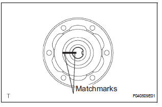
(a) Put matchmarks on both the flanges.
(b) Remove the 4 nuts, bolts and washers.

2. REMOVE INTERMEDIATE SHAFT

(a) Put matchmarks on the propeller shaft subassembly and universal joint flange.
NOTICE: Do not use a punch for the marks.
(b) Using a hexagon wrench (6 mm), remove the 6 bolts and 2 washers and separate the intermediate shaft from the propeller shaft assembly rear.
3. REMOVE CENTER SUPPORT BEARING ASSEMBLY NO.1

(a) Using a chisel and a hammer, loosen the staked part of the nut.
(b) Using SST(s) to hold the front flange, remove the nut and plate washer.
SST 09330-00021
(c) Put matchmarks on the rear flange and shaft.
(d) Hold the intermediate shaft in a vise between aluminium plates.
NOTICE: Do not overtighten the vise

(e) Using SST(s), remove the rear flange.
SST 09950-40011 (09951-04020, 09952-04010, 09953-04030, 09954-04010, 09955-04061, 09957-04010, 09958-04011)
NOTICE: Be careful not to damage the universal joint flange.
(f) Remove the center support bearing assembly No. 1 (rear) and washer.
4. REMOVE CENTER SUPPORT BEARING ASSEMBLY NO.1

(a) Using a chisel and a hammer, loosen the staked part of the nut.
(b) Using SST(s) to hold the front flange, remove the nut and plate washer.
SST 09330-00021

(c) Put matchmarks on the front flange and shaft.
(d) Hold the intermediate shaft in a vise between aluminium plates.
NOTICE: Do not overtighten the vise.

(e) Using SST(s), remove the front flange.
SST 09950-40011 (09951-04020, 09952-04010, 09953-04030, 09954-04010, 09955-04061, 09957-04010, 09958-04011)
NOTICE: Be careful not to damage the universal joint flange.
(f) Remove the center support bearing assembly No. 1 (front) and washer.
 Removal
1. REMOVE EXHAUST PIPE ASSEMBLY
(a) Remove exhaust pipe assembly (See page EX-8).
2. REMOVE PROPELLER W/CENTER BEARING SHAFT ASSEMBLY
(a) Depress the brake pedal and hold it down.
(b) Using ...
 Inspection
1. INSPECT SPIDER BEARING
(a) Check that the spider bearing moves smoothly by
turning the flange.
(b) Check for the looseness around the joint by strongly
moving the flange in the axial and ...
Other materials:
Driving Position Memory Switch Circuit (w/ Memory)
DESCRIPTION
The seat memory switch sends signals to the outer mirror control ECU LH via
the multiplex
communication system to memorize a given seat position. This memory system does
not use a position
sensor. The seat position is detected by counting pulses that are output when
the motor tu ...
Reassembly
1. INSTALL REAR DOOR WIRE SUB-ASSEMBLY LH
Install the wire.
NOTICE:
When installing the wire, push the areas where
the clips are installed in order to prevent
damage and deformation.
Install the 2 screws.
2. INSTALL REAR DOOR LOCK ASSEMBLY LH
Apply MP grease to the slidi ...
Removal
1. REMOVE INSTRUMENT CLUSTER CENTER NO. 1 FINISH PANEL
2. REMOVE INSTRUMENT CLUSTER CENTER NO. 2 FINISH PANEL
3. REMOVE INSTRUMENT CLUSTER FINISH PANEL GARNISH
4. REMOVE RADIO RECEIVER
Remove the 4 screws.
Disconnect the connectors and remove the radio
receiver with bracke ...