Toyota Sienna Service Manual: Driving Position Memory Switch Circuit (w/ Memory)
DESCRIPTION
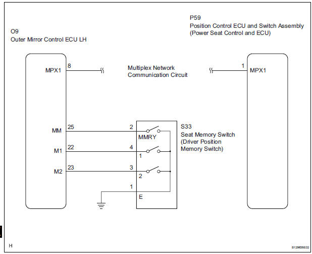
The seat memory switch sends signals to the outer mirror control ECU LH via the multiplex communication system to memorize a given seat position. This memory system does not use a position sensor. The seat position is detected by counting pulses that are output when the motor turns. If there is no pulse output from the motor, the motor will stop operating. The seat memory switch is later used to send signals to the front power seat switch to return the seat to one of the memorized positions.
The power seat memory operation can be performed only when the ignition switch is on and the shift lever is in the P position.
WIRING DIAGRAM
INSPECTION PROCEDURE
1 READ VALUE OF INTELLIGENT TESTER
- Connect the intelligent tester (with CAN VIM) to the DLC3.
- Turn the ignition switch on.
- Read the DATA LIST.
D_SEAT (Position control ECU and switch assembly)

OK: Condition status can be displayed.
PROCEED TO NEXT CIRCUIT INSPECTION SHOWN IN PROBLEM SYMPTOMS TABLE
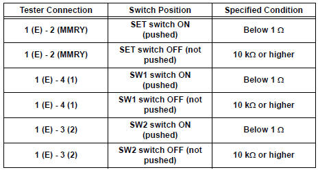
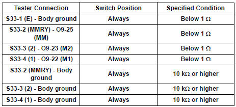
2 INSPECT SEAT MEMORY SWITCH (DRIVING POSITION MEMORY SWITCH)

- Remove the seat memory switch.
- Measure the resistance according to the value(s) in the table below.
Standard resistance
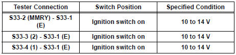
3 CHECK HARNESS AND CONNECTOR (SEAT MEMORY SWITCH CIRCUIT)

- Measure the voltage according to the value(s) in the table below.
Standard voltage
PROCEED TO NEXT CIRCUIT INSPECTION SHOWN IN PROBLEM SYMPTOMS TABLE
4 CHECK HARNESS AND CONNECTOR (OUTER MIRROR CONTROL ECU LH - SEAT MEMORY SWITCH)
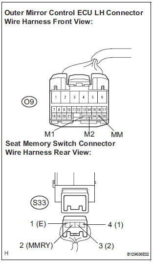
- Disconnect outer mirror control ECU LH connector.
- Measure the resistance according to the value(s) in the table below.
Standard resistance
REPLACE OUTER MIRROR CONTROL ECU LH
 Power Seat Motor Circuit
DESCRIPTION
When the power seat control switch is operated, a command signal is sent to
the position control ECU
and switch assembly (power seat control switch and ECU). The front power seat
swi ...
 ECU Power Source Circuit
DESCRIPTION
The position control ECU and switch assembly (power seat control switch and
ECU) is contained in the
switch assembly.
During manual operation, only one switch signal is accepted. If ...
Other materials:
Sensor signal check by test mode (signal check) (when using intelligent
tester)
(a) When having replaced the skid control ECU and/or
yaw rate and deceleration sensor, perform zero
point calibration of the yaw rate and deceleration
sensor.
HINT:
If the ignition switch is turned from the ON
position to the ACC or off during test mode
(signal check), DTCs of the signal ...
Customizable features
Settings that can be changed using the audio system screen
Settings that can be changed using the multi-information display
Settings that can be changed by your Toyota dealer
Definition of symbols: O = Available, – = Not available
Gauges, meters and multi-information display (, 93)
...
For vehicles equipped with mobile communication systems
FOR VEHICLES EQUIPPED WITH MOBILE COMMUNICATION SYSTEMS
(a) Install the antenna far away from the ECU and
sensors of the vehicle electronic systems as
possible.
(b) Install an antenna feeder at least 20 cm (7.87 in.)
away from the ECU and sensors of the vehicle
electronic systems. For de ...