Toyota Sienna Service Manual: Rear Blower Motor Circuit
DESCRIPTION
Power to the rear blower motor is supplied from the battery via the RR A/C relay.
The rear blower motor speed level varies between 0 and 31 based on the voltage difference measured between the terminals of the motor.
The voltage difference measured between the terminals of the rear blower motor changes in proportion to the control at the rear blower motor controller on the ground side.
WIRING DIAGRAM

INSPECTION PROCEDURE
1 READ VALUE OF INTELLIGENT TESTER
(a) Connect the intelligent tester to the DLC3.
(b) Turn the ignition switch to the ON position and turn the intelligent tester main switch on.
(c) Select the item below in the DATA LIST, and read the display on the intelligent tester.
DATA LIST / AIR CONDITIONER 
OK: The display is as specified in the normal condition.


PROCEED TO NEXT CIRCUIT INSPECTION SHOWN IN PROBLEM SYMPTOMS TABLE
2 INSPECT REAR BLOWER MOTOR
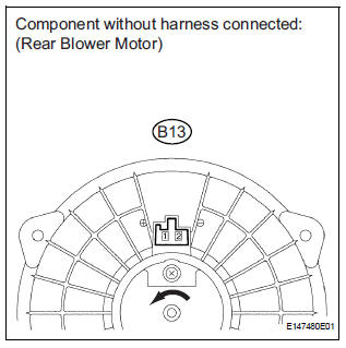
(a) Remove the rear blower motor with the connector still connected.
(b) Disconnect the connector from the rear blower motor.
(c) Connect the positive (+) lead to terminal 1 of the rear blower motor connector, and the negative (-) lead to terminal 2.
OK: The rear blower motor operates smoothly.


3 CHECK HARNESS AND CONNECTOR (REAR BLOWER MOTOR - BATTERY)

(a) Measure the voltage according to the value(s) in the table below.
Standard voltage 


4 CHECK HARNESS AND CONNECTOR (REAR BLOWER MOTOR CONTROLLER - BODY GROUND)

(a) Disconnect the connector from the rear blower motor controller.
(b) Measure the resistance according to the value(s) in the table below.
Standard resistance 


5 CHECK HARNESS AND CONNECTOR (REAR BLOWER MOTOR - REAR BLOWER MOTOR CONTROLLER)

(a) Measure the resistance according to the value(s) in the table below.
Standard resistance 


6 CHECK HARNESS AND CONNECTOR (REAR BLOWER MOTOR CONTROLLER - A/C AMPLIFIER)

(a) Disconnect the connector from the A/C amplifier.
(b) Measure the resistance according to the value(s) in the table below.


7 INSPECT REAR BLOWER MOTOR CONTROLLER

(a) Disconnect the connector from the rear blower motor controller.
(b) Measure the resistance according to the value(s) in the table below.
Standard resistance 

(c) Connect the positive (+) lead to terminal 3 through a 12 V 3.4 W test bulb, and the negative (-) lead to terminal 1.
(d) Connect the three 1.5 V dry cell batteries' positive (+) lead to terminal 2, and the negative (-) lead to terminal 1.
Then check that the test bulb comes on.
OK: The test bulb comes on.


PROCEED TO NEXT CIRCUIT INSPECTION SHOWN IN PROBLEM SYMPTOMS TABLE
 Rear Air Conditioning Relay Circuit
DESCRIPTION
The RR A/C relay is switched on by signals from the A/C amplifier. It
supplies power to the rear blower
motor.
WIRING DIAGRAM
INSPECTION PROCEDURE
1 INSPECT RELAY (RR A/C)
...
 IG Power Source Circuit
DESCRIPTION
The main power source is supplied to the A/C amplifier when the ignition
switch is turned to the ON
position.
The power source is used for operating the A/C amplifier and servo moto ...
Other materials:
A/F Sensor Circuit Slow Response
DTC P2A00 A/F Sensor Circuit Slow Response (Bank 1
Sensor 1)
DTC P2A03 A/F Sensor Circuit Slow Response (Bank 2
Sensor 1)
HINT:
DTC P2A00 indicates malfunctions related to the bank 1 A/F sensor.
DTC P2A03 indicates malfunctions related to the bank 2 A/F sensor.
Bank 1 r ...
DTC check / clear
1. USING INTELLIGENT TESTER
Hook up the intelligent tester to the DLC3.
Monitor the ECU data by following the prompts on
the tester screen.
HINT:
intelligent tester has "Snapshot" function which
records the monitored data. Please refer to the
intelligent tester op ...
Illumination Circuit
DESCRIPTION
Power is supplied to the radio receiver and steering pad switch illumination
when the light control switch is
in the TAIL or HEAD position.
WIRING DIAGRAM
INSPECTION PROCEDURE
NOTICE:
The vehicle is equipped with an SRS (Supplemental Restraint System) which
includes
compon ...