Toyota Sienna Service Manual: Installation
1. INSTALL COMPRESSOR AND MAGNETIC CLUTCH
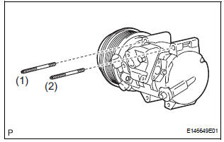
(a) Using a "TORX" socket wrench (E8), install the compressor and magnetic clutch with the 2 stud bolts.
Torque: 10 N*m (102 kgf*cm, 7.4 ft.*lbf)
HINT: Tighten the stud bolts in the order shown in the illustration.

(b) Install the compressor and magnetic clutch with the 2 bolts and the 2 nuts.
Torque: 25 N*m (255 kgf*cm, 18 ft.*lbf)
HINT: Tighten the bolts and nuts in the order shown in the illustration.
(c) Connect the 2 clamps and wire harness.
(d) Connect the connector.
2. INSTALL SUCTION HOSE SUB-ASSEMBLY
(a) Remove the attached vinyl tape from the hose.
(b) Apply sufficient compressor oil to a new O-ring and the fitting surface of the compressor and magnetic clutch.
Compressor oil: ND-OIL 8 or equivalent
(c) Install the O-ring onto the suction hose subassembly.

(d) Install the suction hose sub-assembly onto the compressor and magnetic clutch with the bolt.
Torque: 5.4 N*m (55 kgf*cm, 48 in.*lbf)
3. INSTALL DISCHARGE HOSE SUB-ASSEMBLY
(a) Remove the attached vinyl tape from the hose.
(b) Apply sufficient compressor oil to a new O-ring and the fitting surface of the compressor and magnetic clutch.
Compressor oil: ND-OIL 8 or equivalent
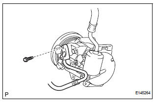
(c) Install the O-ring onto the discharge hose subassembly.
(d) Install the discharge hose sub-assembly onto the compressor and magnetic clutch with the bolt.
Torque: 5.4 N*m (55 kgf*cm, 48 in.*lbf)
4. INSTALL RADIATOR AND FAN ASSEMBLY
(See page CO-39)
5. INSTALL V-RIBBED BELT (See page EM-7)
6. INSTALL FRONT FENDER APRON SEAL RH (See page EM-62)
7. INSTALL FRONT WHEEL RH
8. CHARGE WITH REFRIGERANT (See page AC-173)
9. WARM UP ENGINE
10. INSPECT FOR REFRIGERANT LEAK (See page AC- 173)
 Reassembly
1. INSTALL MAGNETIC CLUTCH ASSEMBLY
(a) Install the magnetic clutch stator while aligning the
protrusion on the stator with the notch on the air
compressor assembly as shown in the illustration ...
 Condenser
COMPONENTS
...
Other materials:
Transmission Fluid Temperature Sensor "A"
Performance
DESCRIPTION
The ATF (Automatic Transmission Fluid) temperature sensor converts the fluid
temperature into a
resistance value which is input into the ECM.
MONITOR DESCRIPTION
The ATF temperature sensor converts the ATF temperature to an electrical
resistance value. Based on
the resis ...
Rear Occupant Classification Sensor LH Collision
Detection
DTC B1787 Rear Occupant Classification Sensor LH Collision
Detection
DESCRIPTION
DTC B1787 is output when the occupant classification ECU receives a collision
detection signal sent by
the rear occupant classification sensor LH if an accident occurs.
DTC B1787 is also output when the front s ...
Removal
1. REMOVE FRONT FENDER LINER LH
2. REMOVE FRONT FENDER LINER RH
3. REMOVE FRONT BUMPER COVER
4. REMOVE FRONT BUMPER ENERGY ABSORBER
5. REMOVE FRONT BUMPER REINFORCEMENT SUBASSEMBLY
6. REMOVE LASER SENSOR
Disconnect the connector and remove the laser the
sensor.
...