Toyota Sienna Service Manual: Installation
1. INSTALL KNOCK CONTROL SENSOR

- Install the 2 knock control sensors with the 2 bolts
as shown in the illustration.
Torque: 20 N*m (204 kgf*cm, 15 ft.*lbf)
- Connect the 2 knock control sensor connectors.
2. INSTALL INTAKE MANIFOLD
3. INSTALL FUEL MAIN TUBE SUB-ASSEMBLY
4. INSTALL INTAKE AIR SURGE TANK
NOTICE: DO NOT apply oil to the bolts listed below.
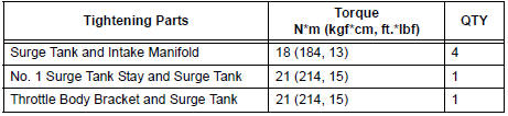
- Install a new gasket to the intake air surge tank [A].
- Using a 5 mm hexagon socket wrench, install the 4
bolts [B].
Torque: 18 N*m (184 kgf*cm, 13 ft.*lbf)
- Install the intake air surge tank with the 2 nuts and 2
bolts [C].
Torque: Nut 16 N*m (163 kgf*cm, 12 ft.*lbf)
Bolt 21 N*m (214 kgf*cm, 15 ft.*lbf)

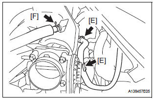
- Connect the connector [D].
- Connect the union to check valve hose [E].
- Connect the ventilation hose No. 2 [F].
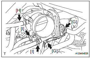
- Install the clamp and connect the throttle with motor body assembly connector [G].
- Connect the vapor feed hose [H].
- Connect the 2 water by-pass hoses to the throttle with motor body assembly [I].
5. INSTALL AIR CLEANER CASE SUB-ASSEMBLY
6. INSTALL AIR CLEANER CAP SUB-ASSEMBLY
7. ADD ENGINE COOLANT
8. INSPECT FOR ENGINE COOLANT LEAK
9. INSPECT FOR FUEL LEAK
10. INSTALL FRONT OUTER COWL TOP PANEL SUBASSEMBLY
11. INSTALL WINDSHIELD WIPER MOTOR ASSEMBLY
12. INSTALL V-BANK COVER SUB-ASSEMBLY
 Inspection
1. KNOCK CONTROL SENSOR
Using an ohmmeter, measure the resistance
between the terminals.
Resistance:
120 to 280 kΩ at 20C (68F)
If the resistance is not specified, replac ...
 EFI relay
Inspection
1. INSPECT EFI RELAY
(a) Using an ohmmeter, measure the resistance
according to the value(s) in the table below.
Standard resistance
If the result is not as specified, replace ...
Other materials:
Bulb locations
Front
Vehicles without daytime running lights or with bulb type daytime
running lights
Headlight high beam and daytime
running lights (if equipped)
Headlight low beam
(halogen bulb)
Fog light (if equipped)
Front turn signal/parking and
front side marker lights
Vehic ...
Initialization
1. RESET
When the back door lock is replaced:
The power back door ECU cannot receive a switch
signal from the lock. This may cause the power
back door system to enter fail-safe mode and DTC
B2215 to set, and also make the system disabled.
When the lock is replaced, be sure to perform t ...
Reassembly
1. INSTALL INPUT SHAFT OIL SEAL RING
(a) Compress a new input shaft oil seal ring from both
sides to reduce dimension A.
Dimension A:
5 mm (0.197 in.)
(b) Coat the oil seal ring with ATF and install it to the
input shaft.
NOTICE:
Do not expand the end gap of the oil seal ring
too much. ...