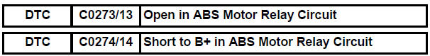
Toyota Sienna Service Manual: Open in ABS Motor Relay Circuit
DESCRIPTION
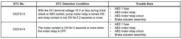
The ABS motor relay supplies power to the ABS pump motor. While the ABS is activated, the ECU turns the motor relay on and operates the ABS pump motor.
If the voltage supplied to the motor relay (+BM) is below the DTCs detection threshold due to low voltage from the battery/alternator, the DTCs may be stored.
WIRING DIAGRAM

INSPECTION PROCEDURE
HINT: After steps 1, 2 and 3 are completed, start the inspection from step 4 when using the intelligent tester, and from step 5 when not using the intelligent tester.
1 INSPECT FUSE (ABS 1 FUSE)
(a) Remove the ABS 1 fuse from the FL block.
(b) Measure the resistance according to the value(s) in the table below.
Standard resistance


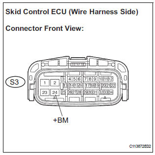
2 INSPECT SKID CONTROL ECU (+BM TERMINAL VOLTAGE)
(a) Install the ABS 1 fuse.
(b) Disconnect the skid control ECU connector.
(c) Measure the voltage according to the value(s) in the table below.
Standard voltage 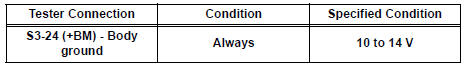

3 INSPECT SKID CONTROL ECU (GND TERMINAL CONTINUITY)
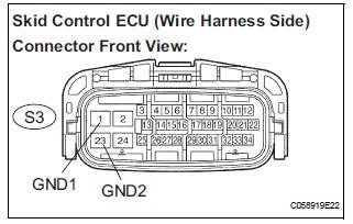
(a) Measure the resistance according to the value(s) in the table below.
Standard resistance 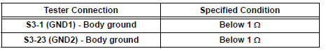


4 PERFORM ACTIVE TEST BY INTELLIGENT TESTER (ABS MOTOR RELAY)
(a) Reconnect the skid control ECU connector.
(b) Connect the intelligent tester to the DLC3.
(c) Turn the ignition switch to the ON position and turn the intelligent tester main switch on.
(d) Start the engine.
(e) Select the ACTIVE TEST mode on the intelligent tester.
ABS: 
(f) Check operating sound of the ABS motor when operating it with the intelligent tester.
OK: The operating sound of the ABS motor is heard.


5 RECONFIRM DTC
(a) Clear the DTCs (See page BC-10).
(b) Start the engine.
(c) Drive the vehicle at the speed of 6 km/h (4 mph) or more.
(d) Check that the same DTCs are recorded (See page BC- 10).
HINT:
- Reinstall the sensors, connectors, etc. and restore the vehicle to its prior condition before rechecking for DTCs.
- If a speed signal of 6 km/h (4 mph) or more is input to the skid control ECU, with the ignition switch on and the stop light switch off, the ECU performs selfdiagnosis of the motor and solenoid circuits.
Result
HINT:
- If any DTCs are output while jiggling a connector or wire harness of the brake actuator (skid control ECU), inspect and repair the connector or wire harness.
- If the normal system code is output, slightly jiggle the connectors, wire harnesses, and fuses of the brake actuator assembly. Make sure that no DTCs are output.
- These DTCs may be stored due to a malfunction in the connector terminal connection, etc.

REPLACE BRAKE ACTUATOR ASSEMBLY
 SFR Solenoid Circuit
DESCRIPTION
The solenoid comes on when signals are received from the ECU and controls the
pressure acting on the
wheel cylinders, thus controlling brake force.
WIRING DIAGRAM
INSPECT ...
 Open in ABS Solenoid Relay Circuit
DESCRIPTION
This relay supplies power to each ABS solenoid.
Immediately after the ignition switch is turned to the ON position, the relay
turns on if the solenoid is
determined to be normal ...
Other materials:
Turning the high beam on/off manually
Switching to low beam
Pull the lever to the original
position.
Switching to high beam
Turn the light switch to the
position.
The Automatic High Beam can be operated when
The engine switch is in the “ON” position (vehicles without a smart key
system)
or IGNITION ON mode (vehicl ...
Disassembly
1. REMOVE REAR DOOR WINDOW FRAME MOULDING
REAR LH (See page ET-31)
2. REMOVE REAR DOOR WINDOW FRAME MOULDING
SUB-ASSEMBLY LH (See page ET-32)
3. REMOVE SLIDE DOOR WINDOW GARNISH LH
Fully open the slide door window.
Remove the glass run.
Using a screwdriver, disengage the clip and rem ...
How to proceed with
troubleshooting
HINT:
Troubleshoot in accordance with the procedures on the
following pages.
1 VEHICLE BROUGHT TO WORKSHOP
2 CUSTOMER PROBLEM ANALYSIS CHECK AND SYMPTOM CHECK
3 INSPECT COMMUNICATION FUNCTION OF LARGE-SCALE MULTIPLEX
COMMUNICATION SYSTEM (BEAN)
Use the intelligent tester to check for norma ...