Toyota Sienna Service Manual: Open in Rear Curtain Shield Squib LH Circuit
DTC B1636/88 Open in Rear Curtain Shield Squib LH Circuit
DESCRIPTION
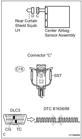
The rear curtain shield squib LH circuit consists of the center airbag sensor assembly and the curtain shield airbag assembly LH.
The circuit instructs the SRS to deploy when deployment conditions are met.
DTC B1636/88 is recorded when an open circuit is detected in the rear curtain shield squib LH circuit.

WIRING DIAGRAM
INSPECTION PROCEDURE
HINT:
- Perform the simulation method by selecting the "check mode" (signal check) with the intelligent tester.
- After selecting the "check mode" (signal check), perform the simulation method by wiggling each connector of the airbag system or driving the vehicle on a city or rough road
1 CHECK CURTAIN SHIELD AIRBAG ASSEMBLY LH (REAR CURTAIN SHIELD SQUIB LH)
- Turn the ignition switch to the LOCK position.
- Disconnect the negative (-) terminal cable from the battery, and wait for at least 90 seconds.
- Disconnect the connectors from the curtain shield airbag assembly LH.
- Connect the white wire side of SST (resistance 2.1 Ω) to
the floor wire.
CAUTION: Never connect a tester to the curtain shield airbag assembly LH (Rear curtain shield squib LH) for measurement, as this may lead to a serious injury due to airbag deployment.
NOTICE: Do not forcibly insert the SST into the terminals of the connector when connecting.
Insert the SST straight into the terminals of the connector.
SST 09843-18060
- Connect the negative (-) terminal cable to the battery, and wait for at least 2 seconds.
- Turn the ignition switch to the ON position, and wait for at least 60 seconds.
- Clear the DTCs stored in memory.
- Turn the ignition switch to the LOCK position.
- Turn the ignition switch to the ON position, and wait for at least 60 seconds.
- Check the DTCs
OK: DTC B1636/88 is not output.
HINT: Codes other than DTC B1636/88 may be output at this time, but they are not related to this check.
REPLACE CURTAIN SHIELD AIRBAG ASSEMBLY LH
2 CHECK FLOOR WIRE (REAR CURTAIN SHIELD SQUIB LH CIRCUIT)

- Turn the ignition switch to the LOCK position.
- Disconnect the negative (-) terminal cable from the battery, and wait for at least 90 seconds.
- Disconnect the SST (resistance 2.1 Ω) from the floor wire.
- Disconnect the connector from the center airbag sensor assembly.
- Measure the resistance according to the value(s) in the table below.
Standard resistance

3 CHECK CENTER AIRBAG SENSOR ASSEMBLY

- Connect the connectors to the curtain shield airbag assembly LH and the center airbag sensor assembly.
- Connect the negative (-) terminal cable to the battery, and wait for at least 2 seconds.
- Turn the ignition switch to the ON position, and wait for at least 60 seconds.
- Clear the DTCs stored in memory.
- Turn the ignition switch to the LOCK position.
- Turn the ignition switch to the ON position, and wait for at least 60 seconds.
- Check the DTCs.
OK: DTC B1636/88 is not output.
HINT: Codes other than DTC B1636/88 may be output at this time, but they are not related to this check.
USE SIMULATION METHOD TO CHECK
 Short in Rear Curtain Shield Squib LH Circuit
DTC B1635/87 Short in Rear Curtain Shield Squib LH Circuit
DESCRIPTION
The rear curtain shield squib LH circuit consists of the center airbag sensor
assembly and the curtain
shield airbag assembl ...
 Short to GND in Rear Curtain Shield Squib LH
Circuit
Short to GND in Rear Curtain Shield Squib LH
Circuit
DTC B1637/85 Short to GND in Rear Curtain Shield Squib LH
Circuit
DESCRIPTION
The rear curtain shield squib LH circuit consists of the center airbag sensor
assembly and the curtain
shield airbag ...
Other materials:
Moving a second seat for third seat access
Getting in the vehicle
Tip-up seats
Pull the seatback angle adjustment
lever and fold down the
seatback. The cushion will tip
up. The seat can slide forward.
Move the seat to the frontmost
position.
Ottoman seats
Pull the seatback angle adjustment
lever and fold down th ...
On-vehicle inspection
1. INSPECT COOLER CONDENSER CORE
(a) If the fin of the cooler condenser core is dirty, clean
it with water and dry it with compressed air.
NOTICE:
Do not damage the fin of the cooler condenser
core.
(b) If the fin of the cooler condenser core is bent, make
it straight using a screwdriver or p ...
Adjusting the set speed
To change the set speed, operate the lever until the desired set speed
is obtained.
Increases the speed
Decreases the speed
Fine adjustment: Momentarily
move the lever in the desired direction.
Large adjustment: Hold the lever in
the desired direction.
The set speed will be incre ...