Toyota Sienna Service Manual: Open in Rear Curtain Shield Squib RH Circuit
DTC B1631/84 Open in Rear Curtain Shield Squib RH Circuit
DESCRIPTION
The rear curtain shield squib RH circuit consists of the center airbag sensor assembly and the curtain shield airbag assembly RH.
The circuit instructs the SRS to deploy when deployment conditions are met.
DTC B1631/84 is recorded when an open circuit is detected in the rear curtain shield squib RH circuit.

WIRING DIAGRAM
INSPECTION PROCEDURE
HINT:
- Perform the simulation method by selecting the "check mode" (signal check) with the intelligent tester.
- After selecting the "check mode" (signal check), perform the simulation method by wiggling each connector of the airbag system or driving the vehicle on a city or rough road
1 CHECK CURTAIN SHIELD AIRBAG ASSEMBLY RH (REAR CURTAIN SHIELD SQUIB RH)

- Turn the ignition switch to the LOCK position.
- Disconnect the negative (-) terminal cable from the battery, and wait for at least 90 seconds.
- Disconnect the connectors from the curtain shield airbag assembly RH.
- Connect the white wire side of SST (resistance 2.1 Ω) to
the floor wire No. 2.
CAUTION: Never connect a tester to the curtain shield airbag assembly RH (Rear curtain shield squib RH) for measurement, as this may lead to a serious injury due to airbag deployment.
NOTICE: Do not forcibly insert the SST into the terminals of the connector when connecting.
Insert the SST straight into the terminals of the connector.
SST 09843-18060
- Connect the negative (-) terminal cable to the battery, and wait for at least 2 seconds.
- Turn the ignition switch to the ON position, and wait for at least 60 seconds.
- Clear the DTCs stored in memory.
- Turn the ignition switch to the LOCK position.
- Turn the ignition switch to the ON position, and wait for at least 60 seconds.
- Check the DTCs
OK: DTC B1631/84 is not output.
HINT: Codes other than DTC B1631/84 may be output at this time, but they are not related to this check.
REPLACE CURTAIN SHIELD AIRBAG ASSEMBLY RH
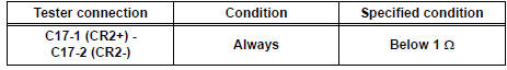
2 CHECK FLOOR WIRE NO.2 (REAR CURTAIN SHIELD SQUIB RH CIRCUIT)

- Turn the ignition switch to the LOCK position.
- Disconnect the negative (-) terminal cable from the battery, and wait for at least 90 seconds.
- Disconnect the SST (resistance 2.1 Ω) from the floor wire No. 2.
- Disconnect the connector from the center airbag sensor assembly.
- Measure the resistance according to the value(s) in the table below.
Standard resistance
3 CHECK CENTER AIRBAG SENSOR ASSEMBLY

- Connect the connectors to the curtain shield airbag assembly RH and the center airbag sensor assembly.
- Connect the negative (-) terminal cable to the battery, and wait for at least 2 seconds.
- Turn the ignition switch to the ON position, and wait for at least 60 seconds.
- Clear the DTCs stored in memory.
- Turn the ignition switch to the LOCK position.
- Turn the ignition switch to the ON position, and wait for at least 60 seconds.
- Check the DTCs.
OK: DTC B1631/84 is not output.
HINT: Codes other than DTC B1631/84 may be output at this time, but they are not related to this check.
USE SIMULATION METHOD TO CHECK
 Short in Rear Curtain Shield Squib RH Circuit
DTC B1630/83 Short in Rear Curtain Shield Squib RH Circuit
DESCRIPTION
The rear curtain shield squib RH circuit consists of the center airbag sensor
assembly and the curtain
shield airbag assembl ...
 Short to GND in Rear Curtain Shield Squib RH
Circuit
Short to GND in Rear Curtain Shield Squib RH
Circuit
DTC B1632/81 Short to GND in Rear Curtain Shield Squib RH
Circuit
DESCRIPTION
The rear curtain shield squib RH circuit consists of the center airbag sensor
assembly and the curtain
shield airbag ...
Other materials:
Short to B+ in Door System Communication
Bus Malfunction/ Short to GND in Door System Communication
Bus Malfunction
DTC B1214 Short to B+ in Door System Communication
Bus Malfunction
DTC B1215 Short to GND in Door System Communication
Bus Malfunction
DESCRIPTION
DTCs B1214 and B1215 are output when a short to +B or the body ground occurs
on the communication
bus. Detecting this condition disables all the ...
Rear Occupant Classification Sensor RH Collision
Detection
DTC B1788 Rear Occupant Classification Sensor RH Collision
Detection
DESCRIPTION
DTC B1788 is output when the occupant classification ECU receives a collision
detection signal sent by
the rear occupant classification sensor RH if an accident occurs.
DTC B1788 is also output when the front s ...
Display contents
The multi-information display presents
the driver with a variety of
vehicle data.
Menu icons
Displays the following information when an icon is selected.
Some of the information may be displayed automatically depending
on the situation.
Drive information
Select to display various ...