Toyota Sienna Service Manual: Reassembly
1. INSTALL CENTER SUPPORT BEARING ASSEMBLY NO.1

(a) Set the center support bearing assembly No. 1 (front) to the intermediate shaft, as shown in the illustration.
(b) Install a new washer to the intermediate shaft.
NOTICE: Be sure to install the bearing in the correct direction.

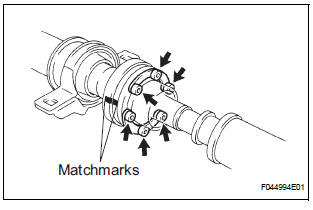
(c) Align the matchmarks on the front flange and shaft, and place the flange on the shaft.

(d) Using SST(s) to hold the front flange, press the center support bearing assembly No. 1 (front) into the position by tightening down with a new nut and plate washer.
SST 09330-00021 Torque: 181 N*m (1,850 kgf*cm, 134 ft.*lbf)
(e) Loosen the nut.
(f) Torque the nut again.
Torque: 69 N*m (700 kgf*cm, 51 ft.*lbf)
(g) Using a chisel and a hammer, stake the nut.
2. INSTALL CENTER SUPPORT BEARING ASSEMBLY NO.1

(a) Set the center support bearing assembly No. 1 (rear) on the shaft, as shown in the illustration.
(b) Install a new washer to the shaft.
NOTICE: Be sure to install the bearing in the correct direction.

(c) Align the matchmarks on the rear flange and shaft, and place the flange on the shaft.

(d) Using SST(s) to hold the front flange, press the center support bearing assembly No. 1 (rear) into the position by tightening down with a new nut and plate washer.
SST 09330-00021 Torque: 181 N*m (1,850 kgf*cm, 134 ft.*lbf)
(e) Loosen the nut.
(f) Torque the nut again.
Torque: 69 N*m (700 kgf*cm, 51 ft.*lbf)
(g) Using a chisel and a hammer, stake the nut.
3. INSTALL INTERMEDIATE SHAFT
(a) Align the matchmarks on the intermediate shaft and rear propeller shaft assembly rear, then install the 2 washers and 6 bolts.
(b) Using a hexagon wrench (6 mm), loosely tighten the 6 bolts.
4. INSTALL PROPELLER SHAFT ASSEMBLY
(a) Align the matchmarks on the propeller shaft assembly flange and front flange, and connect the shaft with the 4 bolts, washers and nuts.
Torque: 74 N*m (750 kgf*cm, 54 ft.*lbf)

(b) Check that each joint of the propeller shaft is facing in the correct direction, as shown in the illustration below.

 Inspection
1. INSPECT SPIDER BEARING
(a) Check that the spider bearing moves smoothly by
turning the flange.
(b) Check for the looseness around the joint by strongly
moving the flange in the axial and ...
 Installation
1. INSTALL PROPELLER W/CENTER BEARING SHAFT ASSEMBLY
(a) Align the matchmarks on the propeller shaft
assembly rear flange and differential companion
flange, and connect the shaft with the 4 bol ...
Other materials:
Child restraint systems with a top tether strap (third seat)
Center seat
Secure the child restraint
system using the seat belt or
LATCH anchors. Adjust the
head restraint to the uppermost
position.
Latch the hook onto the
anchor bracket and tighten
the top tether strap.
Make sure the top tether strap is
securely latched.
...
Brake System Malfunction
DTC P1578 Brake System Malfunction
DESCRIPTION
This DTC is output when the VSC system has a problem. Check the VSC system
when this DTC is
output
DTC No.
DTC Detection Condition
Trouble Area
P1578
The ECM receives a brake system error signal for 0.2
...
Short to B+ in Front Passenger Side Squib Circuit
DTC B0108/52 Short to B+ in Front Passenger Side Squib Circuit
DESCRIPTION
The front passenger side squib circuit consists of the center airbag sensor
assembly and the front
passenger airbag assembly.
The circuit instructs the SRS to deploy when deployment conditions are met.
DTC B0108/52 ...