Toyota Sienna Service Manual: Removal
1. DRAIN BRAKE FLUID
NOTICE: Wash brake fluid off immediately if it adheres to any painted surface.
2. DISCONNECT BATTERY NEGATIVE TERMINAL
3. REMOVE AIR CLEANER ASSEMBLY WITH HOSE
4. REMOVE BRAKE ACTUATOR WITH BRACKET

(a) Release the latch of the brake actuator connector to disconnect the connector (b) Using SST, disconnect the 6 brake tubes from the actuator with bracket.
SST 09023-00101
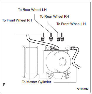
(c) Use tags or make a memo to identify the places to reconnect.

(d) Remove the 3 bolts and the actuator with bracket.
NOTICE: Be careful not to damage the brake tubes and wire harness.
5. REMOVE BRAKE ACTUATOR
(a) Remove the 2 nuts and the brake actuator assembly from the brake actuator bracket.
 On-vehicle inspection
1. CONNECT INTELLIGENT TESTER
(a) Connect the intelligent tester to the DLC3.
(b) Start the engine and run at idle.
(c) Select the ACTIVE TEST mode on the intelligent
tester.
HINT:
Pleas ...
 Installation
1. INSTALL BRAKE ACTUATOR
(a) Install the brake actuator assembly with the 2 nuts.
Torque: 5.4 N*m (55 kgf*cm, 48 in.*lbf)
2. INSTALL BRAKE ACTUATOR WITH BRACKET
(a) Install the actuator wit ...
Other materials:
Front Clearance Sonar Sensor LH Circuit
DESCRIPTION
An ultrasonic sensor consists of a sensor portion that transmits and receives
ultrasonic waves and a preamplifier
that amplifies them. The ultrasonic sensor outputs the ultrasonic waves and
sends the received
signals to the clearance warning ECU.
WIRING DIAGRAM
INSPECTION PROC ...
Removal
1. REMOVE INSTRUMENT CLUSTER FINISH PANEL
CENTER NO.1 (See page IP-8)
2. REMOVE INSTRUMENT CLUSTER FINISH PANEL
CENTER NO.2
3. REMOVE SHIFT LEVER KNOB SUB-ASSEMBLY
HINT:
(See page AX-146 for U151E, AX-146 for U151F)
4. REMOVE INSTRUMENT CLUSTER FINISH PANEL
ASSEMBLY CENTER (See page IP-9)
5 ...
Oxygen (A/F) Sensor Heater Control Circuit
HINT
Although the DTC titles say the oxygen sensor, these DTCs relate to the
Air-Fuel Ratio (A/F) sensor.
Sensor 1 refers to the sensor mounted in front of the Three-Way
Catalytic Converter (TWC) and
located near the engine assembly.
DESCRIPTION
Refer to DTC P2195 (See page ES- ...