Toyota Sienna Service Manual: Removal
1. Drain automatic transaxle fluid
(a) Remove the drain plug, gasket and drain ATF.
(b) Install a new gasket and the drain plug.
Torque: 49 N*m (500 kgf*cm, 36 ft.*lbf)
2. Drain transfer oil (for 4wd)
Hint: (see page tf-8)
3. Remove front wheel
4. REMOVE FRONT AXLE HUB LH NUT
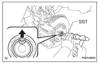
(a) Using SST and a hammer, unstake the staked part of the axle hub LH nut.
SST 09930-00010
NOTICE: Loosen the staked part of the nut completely, otherwise the screw of the drive shaft may be damaged.
(b) While applying the brakes, remove the lock axle hub LH nut.
5. SEPARATE FRONT STABILIZER LINK ASSEMBLY LH
(a) Remove the nut, and separate the stabilizer link assembly LH.

HINT: If the ball joint turns together with the nut, use a hexagon wrench (6 mm) to hold the stud.
6. SEPARATE SPEED SENSOR FRONT LH

(a) Remove the bolt and clip, and separate the sensor wire and hose from the shock absorber.
NOTICE: Be careful not to damage the speed sensor.

(b) Remove the bolt, and separate the speed sensor from LH from the steering knuckle.
NOTICE: Prevent foreign matter from adhering to the speed sensor.
7. SEPARATE TIE ROD END SUB-ASSEMBLY LH

(a) Remove the cotter pin and nut.
(b) Using SST, separate the tie rod end from the steering knuckle.
SST 09628-62011
8. SEPARATE NO. 1 FRONT SUSPENSION ARM SUBASSEMBLY LOWER LH

(a) Remove the bolt and 2 nuts, and separate the No. 1 front suspension arm sub-assembly lower from the lower ball joint.
9. SEPARATE FRONT AXLE ASSEMBLY LH

(a) Using a plastic hammer, separate the drive shaft from the axle hub.
NOTICE: Be careful not to damage the boot and speed sensor rotor
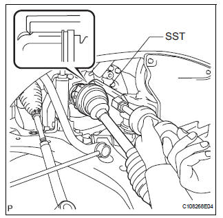
10. REMOVE FRONT DRIVE SHAFT ASSEMBLY LH

(a) Using SST, remove the front drive shaft assembly LH.
SST 09520-01010, 09520-24010 (09520-32040)
NOTICE:
- Be careful not to damage the transaxle case oil seal, inboard joint boot and drive shaft dust cover.
- Be careful not to drop the drive shaft assembly.
11. REMOVE FRONT DRIVE SHAFT ASSEMBLY RH (for 2WD)

(a) Using a screwdriver, remove the bearing brake hole snap ring.
(b) Remove the bolt and front drive shaft assembly RH from the drive shaft bearing bracket.
12. REMOVE FRONT DRIVE SHAFT ASSEMBLY RH (for 4WD)
(a) Using SST, remove the front drive shaft assembly RH.
SST 09520-01010, 09520-24010 (09520-32040)
HINT: Overhaul the side following the same procedures as for the LH side.
NOTICE:
- When removing and installing the front drive
shaft assembly RH in 4WD vehicle, be sure to
first drain all the transaxle oil and transfer oil.
If removal and installation is carried out without draining these oils, the transfer oil will flow into the transaxle side. Extensive cleaning will be required if the two oils mix.
- Do not damage the oil seal and dust cover.
- Move the drive shaft assembly while keeping it level.
13. SECURE FRONT AXLE ASSEMBLY

NOTICE: The hub bearing could be damaged if it is subjected to the vehicle weight, such as when moving the vehicle with the drive shaft removed. Therefore, if it is absolutely necessary to place the vehicle weight on the hub bearing, first support it with SST.
SST 09608-16042 (09608-02021, 09608-02041)
 Front drive shaft
COMPONENTS
...
 Disassembly
1. REMOVE NO. 2 FRONT AXLE INBOARD JOINT BOOT LH CLAMP
(a) Using pliers, remove the No. 2 front axle inboard
joint boot LH clamp, as shown in the illustration.
2. REMOVE FRONT AXLE INBOARD JOIN ...
Other materials:
No. 2 Clearance Warning Buzzer Circuit
DESCRIPTION
The clearance warning ECU receives the ultrasonic sensor signal to sound the
rear warning buzzer.
WIRING DIAGRAM
INSPECTION PROCEDURE
1 CHECK HARNESS AND CONNECTOR (CLEARANCE WARNING ECU - AIR CONDITIONER
AMPLIFIER)
Disconnect the connectors from the clearance warning ...
For manual air conditioning system
ON-VEHICLE INSPECTION
1. INSPECT AIR INLET CONTROL SERVO MOTOR
(a) Remove the air inlet control servo motor.
(b) Connect the positive (+) lead from the battery to
terminal 5 and negative (-) lead to terminal 1, then
check that the lever turns to "RECIRCULATION"
side smoothly.
...
Front wheel alignment
Adjustment
NOTICE:
For vehicles equipped with VSC, if wheel alignment has
been adjusted, and if suspension or underbody
components have been removed/installed or replaced, be
sure to perform the following initialization procedure in
order for the system to function normally:
1. Disconnect the ...