Toyota Sienna Service Manual: Side Airbag Sensor Assembly RH Circuit Malfunction
DTC B1140/32 Side Airbag Sensor Assembly RH Circuit Malfunction
DESCRIPTION
The side airbag sensor RH circuit consists of the center airbag sensor assembly and side airbag sensor RH.
If the center airbag sensor assembly receives signals from the side airbag sensor RH, it judges whether or not the SRS should be activated.
DTC B1140/32 is recorded when a malfunction in the side airbag sensor RH circuit is detected.

WIRING DIAGRAM

INSPECTION PROCEDURE
1 CHECK DTC

- Turn the ignition switch to the ON position, and wait for at least 60 seconds.
- Clear the DTCs stored in memory.
- Turn the ignition switch to the LOCK position.
- Turn the ignition switch to the ON position, and wait for at least 60 seconds.
- Check the DTCs.
OK: DTC B1140/32 is not output.
HINT: Codes other than DTC B1140/32 may be output at this time, but they are not related to this check.
USE SIMULATION METHOD TO CHECK
2 CHECK CONNECTION OF CONNECTORS
- Turn the ignition switch to the LOCK position.
- Disconnect the negative (-) terminal cable from the battery, and wait for at least 90 seconds.
- Check that the connectors are properly connected to the center airbag sensor assembly and the side airbag sensor RH.
OK: The connectors are connected.
3 CHECK FLOOR WIRE NO. 2 (OPEN)

- Disconnect the connectors from the center airbag sensor assembly and the side airbag sensor RH.
- Using a service wire, connect A22-17 (VUPR) and A22- 15 (ESR) of connector "B".
NOTICE: Do not forcibly insert a service wire into the terminals of the connector when connecting.
- Measure the resistance according to the value(s) in the table below.
Standard resistance


- Using a service wire, connect A22-16 (SSR+) and A22-
13 (SSR-) of connector "B".
NOTICE: Do not forcibly insert a service wire into the terminals of the connector when connecting.
- Measure the resistance according to the value(s) in the table below.
Standard resistance

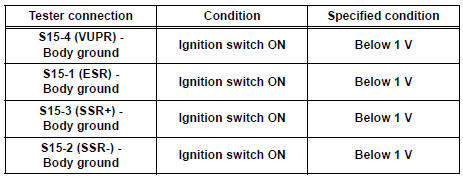
4 CHECK FLOOR WIRE NO. 2 (SHORT TO B+)

- Disconnect the service wire from connector "B".
- Connect the negative (-) terminal cable to the battery, and wait for at least 2 seconds.
- Turn the ignition switch to the ON position.
- Measure the voltage according to the value(s) in the table below.
Standard voltage
5 CHECK FLOOR WIRE NO. 2 (SHORT TO GROUND)

- Turn the ignition switch to the LOCK position.
- Disconnect the negative (-) terminal cable from the battery, and wait for at least 90 seconds.
- Measure the resistance according to the value(s) in the table below.
Standard resistance

6 CHECK FLOOR WIRE NO. 2 (SHORT)

- Measure the resistance according to the value(s) in the table below.
Standard resistance

7 CHECK SIDE AIRBAG SENSOR RH

- Connect the connector to the center airbag sensor assembly.
- Interchange the side airbag sensor RH with LH and connect the connectors to them.
- Connect the negative (-) terminal cable to the battery, and wait for at least 2 seconds.
- Turn the ignition switch to the ON position, and wait for at least 60 seconds.
- Clear the DTCs stored in memory.
- Turn the ignition switch to the LOCK position.
- Turn the ignition switch to the ON position, and wait for at least 60 seconds.
- Check the DTCs.
Result

HINT: Codes other than DTC B1140/32 and B1141/33 may be output at this time, but they are not related to this check.
USE SIMULATION METHOD TO CHECK
 Half Connection in Center Airbag Sensor
Assembly Connectors
Half Connection in Center Airbag Sensor
Assembly Connectors
DTC B1135/24 Half Connection in Center Airbag Sensor
Assembly Connectors
DESCRIPTION
The center airbag sensor assembly connector has a mechanism that electrically
detects half connection.
The ...
 Side Airbag Sensor Assembly LH Circuit Malfunction
DTC B1141/33 Side Airbag Sensor Assembly LH Circuit Malfunction
DESCRIPTION
The side airbag sensor LH circuit consists of the center airbag sensor
assembly and side airbag sensor
LH.
If the ce ...
Other materials:
Terminals of ECU
1. TELEVISION CAMERA ASSEMBLY
Disconnect the T10 camera connector
Measure the voltage and resistance of each
terminal of the wire harness side connector.
If the result is not as specified, there may be a
malfunction on the wire harness side.
Reconnect the T10 ...
Eject Error/ Elevator Error/ Clamp Error/ Eject Error/ Elevator Error/ Clamp
Error
DTC 62-45 Eject Error
DTC 62-51 Elevator Error
DTC 62-52 Clamp Error
DTC 63-45 Eject Error
DTC 63-51 Elevator Error
DTC 63-52 Clamp Error
DESCRIPTION
DTC No.
DTC Detecting Condition
Trouble Area
62-45
Disc cannot be ejected.
Radio receiver
62-5 ...
Fuel tank
Components
REMOVAL
1. DISCHARGE FUEL SYSTEM PRESSURE
(See page FU-1)
2. REMOVE CHARCOAL CANISTER PROTECTOR (See
page FU-30)
3. REMOVE REAR FLOOR NO. 2 CROSSMEMBER BRACE LH
(a) Remove the 2 bolts and the rear floor No. 2
crossmember brace LH.
4. REMOVE FUEL TANK FILLER HOSE COVER ...