Toyota Sienna Service Manual: Side Airbag Sensor Assembly LH Circuit Malfunction
DTC B1141/33 Side Airbag Sensor Assembly LH Circuit Malfunction
DESCRIPTION
The side airbag sensor LH circuit consists of the center airbag sensor assembly and side airbag sensor LH.
If the center airbag sensor assembly receives signals from the side airbag sensor LH, it judges whether or not the SRS should be activated.
DTC B1141/33 is recorded when a malfunction in the side airbag sensor LH circuit is detected.

WIRING DIAGRAM

INSPECTION PROCEDURE
1 CHECK DTC

- Turn the ignition switch to the ON position, and wait for at least 60 seconds.
- Clear the DTCs stored in memory.
- Turn the ignition switch to the LOCK position.
- Turn the ignition switch to the ON position, and wait for at least 60 seconds.
- Check the DTCs.
OK: DTC B1141/33 is not output.
HINT: Codes other than DTC B1141/33 may be output at this time, but they are not related to this check.
USE SIMULATION METHOD TO CHECK2 CHECK CONNECTION OF CONNECTORS
- Turn the ignition switch to the LOCK position.
- Disconnect the negative (-) terminal cable from the battery, and wait for at least 90 seconds.
- Check that the connectors are properly connected to the center airbag sensor assembly and the side airbag sensor LH.
OK: The connectors are connected.
3 CHECK FLOOR WIRE (OPEN)

- Disconnect the connectors from the center airbag sensor assembly and the side airbag sensor LH.
- Using a service wire, connect A20-16 (VUPL) and A20-
18 (ESL) of connector "B".
NOTICE: Do not forcibly insert a service wire into the terminals of the connector when connecting.
- Measure the resistance according to the value(s) in the table below.
Standard resistance


- Using a service wire, connect A20-17 (SSL+) and A20-
20 (SSL-) of connector "B".
NOTICE: Do not forcibly insert a service wire into the terminals of the connector when connecting.
- Measure the resistance according to the value(s) in the table below.
Standard resistance

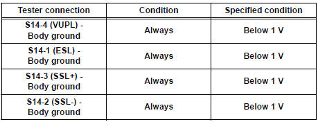
4 CHECK FLOOR WIRE (SHORT TO B+)

- Disconnect the service wire from connector "B".
- Connect the negative (-) terminal cable to the battery, and wait for at least 2 seconds.
- Turn the ignition switch to the ON position.
- Measure the voltage according to the value(s) in the table below.
Standard voltage
5 CHECK FLOOR WIRE (SHORT TO GROUND)

- Turn the ignition switch to the LOCK position.
- Disconnect the negative (-) terminal cable from the battery, and wait for at least 90 seconds.
- Measure the resistance according to the value(s) in the table below.
Standard resistance

6 CHECK FLOOR WIRE (SHORT)

- Measure the resistance according to the value(s) in the table below
Standard resistance

7 CHECK SIDE AIRBAG SENSOR LH

- Connect the connector to the center airbag sensor assembly.
- Interchange the side airbag sensor RH with LH and connect the connectors to them.
- Connect the negative (-) terminal cable to the battery, and wait for at least 2 seconds.
- Turn the ignition switch to the ON position, and wait for at least 60 seconds.
- Clear the DTCs stored in memory.
- Turn the ignition switch to the LOCK position.
- Turn the ignition switch to the ON position, and wait for at least 60 seconds.
- Check the DTCs.
Result

HINT: Codes other than DTC B1140/32 and B1141/33 may be output at this time, but they are not related to this check.
USE SIMULATION METHOD TO CHECK
 Side Airbag Sensor Assembly RH Circuit Malfunction
DTC B1140/32 Side Airbag Sensor Assembly RH Circuit Malfunction
DESCRIPTION
The side airbag sensor RH circuit consists of the center airbag sensor
assembly and side airbag sensor
RH.
If the ce ...
 Front Airbag Sensor RH Circuit Malfunction
DTC B1148/36 Front Airbag Sensor RH Circuit Malfunction
DESCRIPTION
The front airbag sensor RH circuit consists of the center airbag sensor
assembly and front airbag sensor
RH. If the center airb ...
Other materials:
Removal
1. Remove rear wheel
2. Remove exhaust pipe assembly
Hint:
(see page ex-8)
3. Remove propeller with center bearing
shaft assembly
Hint:
(see page pr-3)
4. REMOVE REAR DIFFERENTIAL FILLER PLUG
(A) using a hexagon wrench (10 mm), remove the filler
plug and gasket.
5. Remove rear differentia ...
Open in Stop Light Switch Circuit
DTC C1249/49 Open in Stop Light Switch Circuit
DESCRIPTION
This skid control ECU inputs the stop light switch signal and detects the
status of brake operation.
The skid control ECU has an open detection circuit. If an open in the stop light
switch input line or GND
side stop light circuit ...
Evaporative Emission Control System Leak
Detected
DTC P0455 Evaporative Emission Control System Leak
Detected (Gross Leak)
DTC P0456 Evaporative Emission Control System Leak
Detected (Very Small Leak)
DTC SUMMARY
DESCRIPTION
The circuit description can be found in the EVAP (Evaporative Emission)
System.
INSPECTION PROCEDURE
Refer to t ...