Toyota Sienna Service Manual: Tachometer Malfunction
DESCRIPTION
The meter CPU receives the engine revolution signal from the ECM via the direct lines. The meter CPU displays engine revolution data that is calculated based on the data received from the ECM.
WIRING DIAGRAM

INSPECTION PROCEDURE
1 PERFORM ACTIVE TEST BY INTELLIGENT TESTER
- Connect the intelligent tester to the DLC3.
- Turn the switch to the ON position.
- Turn the tester ON.
- Enter the following menus: DIAGNOSIS / OBD/MOBD / METER / ACTIVE TEST.
- Check the operation by referring to the values in the table below.
METER:

OK: Needle indication is normal.
2 READ VALUE OF INTELLIGENT TESTER (ENGINE SPEED SIGNAL)
- Connect the intelligent tester to the DLC3.
- Turn the switch to the ON position.
- Turn the tester ON.
- Enter the following menus: DIAGNOSIS / OBD/MOBD / METER / DATA LIST.
- Check the values by referring to the values in the table below
METER:

OK: Engine speed displayed on the tester is almost the same as the actual engine speed.
REPLACE COMBINATION METER ASSEMBLY
3 READ VALUE OF INTELLIGENT TESTER (ENGINE SPEED SIGNAL)
- Connect the intelligent tester to the DLC3.
- Turn the switch to the ON position.
- Turn the tester ON.
- Enter the following menus: DIAGNOSIS / OBD/MOBD / ENGINE / ACTIVE TEST.
- Check the values by referring to the values in the table below.
ENGINE:

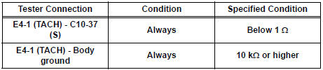
4 CHECK HARNESS AND CONNECTOR (COMBINATION METER - ECM)

- Disconnect the E4 and C10 connectors.
- Measure the resistance according to the value(s) in the table below.
Standard resistance
5 INSPECT COMBINATION METER ASSEMBLY

- Check the input signal waveform.
- Remove the combination meter with the connector still connected.
- Connect the oscilloscope to terminal C10-37 (S) and body ground.
- Start the engine.
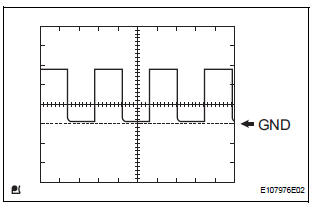
- Check the signal waveform according to the condition(s) in the table below.

OK: The waveform is displayed as shown in the illustration
REPLACE ECM
 Speedometer Malfunction
DESCRIPTION
Factors that affect the indicated vehicle speed include tire size, tire
inflation, and tire wear. The speed indicated on the speedometer has an
allowable margin of error. This can be ...
 Fuel Receiver Gauge Malfunction
DESCRIPTION
The meter CPU uses the fuel sender gauge assembly to determine the level of
the fuel in the fuel tank.
The resistance of the fuel sender gauge will vary between approximately 15 ] ...
Other materials:
Brake Switch "A" Circuit
DTC P0571 Brake Switch "A" Circuit
DESCRIPTION
When the brake pedal is depressed, the stop light switch sends a signal to
the ECM. When the ECM
receives this signal, it cancels the cruise control. The fail-safe function
operates to enable normal driving
even if there is a malfuncti ...
Perform monitor drive pattern
The monitor results and test values can be checked with
the OBD II scan tool or the intelligent tester. The engine
control module (ECM) monitors the emissions-related
components such as the thermostat, catalyst converter
and evaporative emissions (EVAP), and determines
whether they are function ...
Cooling fan ecu
ON-VEHICLE INSPECTION
1. INSPECT COOLING FAN ECU
(a) Inspect the input voltage.
(1) Disconnect the cooling fan ECU connector.
(2) Turn the ignition switch to the ON position.
Check the voltage of the +B terminal of the
disconnected wire harness side connector.
Standard voltage:
9 t ...