Toyota Sienna Service Manual: When servicing full-time 4wd vehicles
The full-time 4WD SIENNA is equipped with the open center differential system.
If incorrect preparations or test procedures are used, the test will not only be unsuccessful, but may be dangerous as well.
Therefore, before beginning any such servicing or test, be sure to check the following items:
- Whether wheels should be touching ground or jacked up
- Transaxle gear position
- Maximum testing vehicle speed
- Maximum testing time
(a) Before Beginning Test
This vehicle does not have a center diff. lock mode or 4WD (Normal) Mode to allow only the front or rear wheel to be rotated.
The test method for this vehicle is different from that for vehicles equipped with the center diff. lock mode or 4WD (Normal) Mode, so make sure to use the correct test method.
 Braking Force Test
(Vehicle Speed: Below 0.5 km/h or 0.3 mph) When performing low-speed type brake tester measurements, observe the following instructions.
(1) Position the wheels to be tested (front or rear) on the tester.
(2) Shift the transaxle shift lever to "N" position.
(3) Idle the engine, operate the brake booster and perform the test.
(c) Speedometer Test or Other Tests
(Using Speedometer Tester or Chassis Dynamometer)
When performing test at high speed or high load, use the methods shown below.
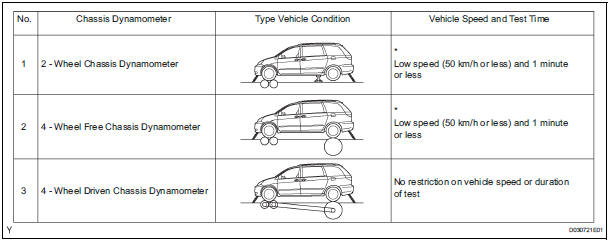
*: This is to avoid damaging the center differential.
(d) On-Vehicle Wheel Balancing

On-Vehicle Wheel Balancing
When doing on-vehicle wheel balancing on a fulltime 4WD vehicle, to prevent the wheels from rotating at different speeds in different directions from each other (which could damage the center differential), always be sure to observe the following precautions:
(1) All 4 wheels should be jacked up, clearing the ground completely.
(2) The parking brake lever should be fully released.
(3) None of the brakes should be allowed to drag.
(4) The wheels should be driven on the wheel balancer with the engine running.
HINT:
When doing this, be careful of the other wheels, which will rotate at the same time.
(5) Avoid sudden acceleration, deceleration and braking.
(6) Carry out wheel balancing with the transaxle in D position.
 For vehicles equipped with mobile communication systems
FOR VEHICLES EQUIPPED WITH MOBILE COMMUNICATION SYSTEMS
(a) Install the antenna far away from the ECU and
sensors of the vehicle electronic systems as
possible.
(b) Install an antenna feeder ...
 For vehicles equipped with traction control (trac) system
When using a 2-wheel drum tester such as a
speedometer tester or chassis dynamometer, etc., or
jacking up the front wheels and driving the wheels,
always push in the TRAC cut ("TRAC OFF") ...
Other materials:
Disposal
HINT:
When scrapping a vehicle equipped with the SRS or
disposing of the front passenger airbag assembly, be sure to
deploy the airbag first in accordance with the procedure
described below. If any abnormality occurs with airbag
deployment, contact the SERVICE DEPT. of the TOYOTA
MOTOR SALES, ...
Knock Sensor 1 Circuit Low Input
DESCRIPTION
A flat type knock sensor (non-resonant type) has a structure that can detect
vibrations over a wide band of
frequencies: between approximately 6 kHz and 15 kHz.
Knock sensors are fitted onto the engine block to detect engine knocking.
The knock sensor contains a piezoelectr ...
Inspection
1. INSPECT ENGINE COOLANT TEMPERATURE SENSOR
Using an ohmmeter, measure the resistance
between the terminals.
Standard resistance
If the result is as specified, do not replace the
engine coolant temperature sensor.
If the result is not as specified, replace the
engine ...