Toyota Sienna Service Manual: Indicator Circuit
DESCRIPTION
This system has two indicator lights. One of the indicator lights is built into the fold seat switch. This indicator light receives power from the fold seat control ECU. It comes on or blinks when the system detects that an object is caught or when the seat operation conditions are not met.
The other indicator light is on the combination meter. This indicator light comes on when the reclining motor or fold seat control ECU is not initialized, any seat legs are released, or when the seatback is outside the reclining operation range.
WIRING DIAGRAM
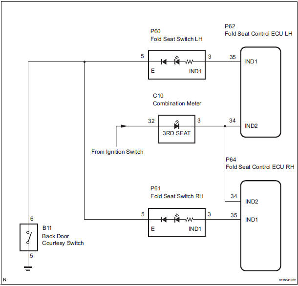
INSPECTION PROCEDURE
HINT:
- When the indicator light on the fold seat switch does not come on, start troubleshooting from step 1.
- When the indicator light on the combination meter does not come on, start troubleshooting from step 6.
1 INSPECT FOLD SEAT SWITCH

- Remove the fold seat switch.
- Disconnect the connector from the fold seat switch.
- Connect the positive (+) lead from the battery terminal 3 and negative (-) lead to terminal 5, and check that the indicator light comes on.
OK: Indicator light comes on.
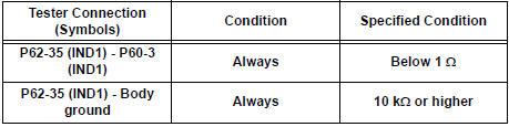
2 CHECK HARNESS AND CONNECTOR (FOLD SEAT CONTROL ECU - FOLD SEAT SWITCH)
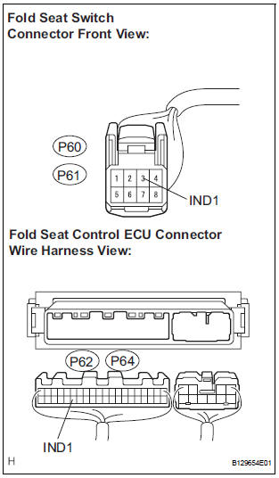
- Disconnect the connector from the fold seat control ECU.
- Measure the resistance according to the value(s) in the table below.
Standard resistance LH side
RH side

3 CHECK HARNESS AND CONNECTOR (FOLD SEAT SWITCH - BACK DOOR COURTESY SWITCH)

- Disconnect the connector from the back door courtesy switch.
- Measure the resistance according to the value(s) in the table below.
Standard resistance LH side

RH side

4 INSPECT BACK DOOR COURTESY SWITCH

- Measure the resistance according to the value(s) in the table below.
Standard resistance

5 CHECK HARNESS AND CONNECTOR (BACK DOOR COURTESY SWITCH - BODY GROUND)

- Measure the resistance according to the value(s) in the table below.
Standard resistance

PROCEED TO NEXT CIRCUIT INSPECTION SHOWN IN PROBLEM SYMPTOMS TABLE
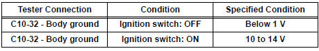
6 CHECK HARNESS AND CONNECTOR (COMBINATION METER - BATTERY)
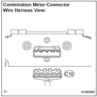
- Remove the combination meter.
- Disconnect the connector from the combination meter.
- Measure the voltage according to the value(s) in the table below.
Standard voltage
7 CHECK HARNESS AND CONNECTOR (COMBINATION METER - FOLD SEAT CONTROL ECU)
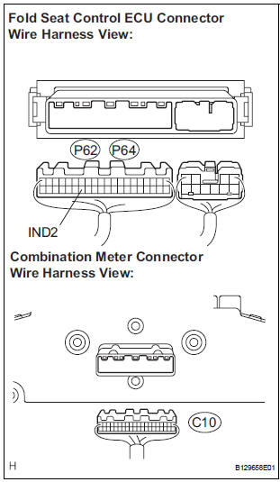
- Disconnect the connector from the fold seat control ECU.
- Measure the resistance according to the value(s) in the table below.
Standard resistance LH side

RH side

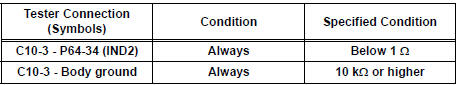
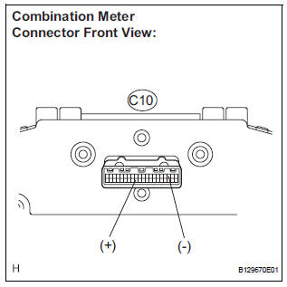
8 INSPECT COMBINATION METER (3rd SEAT INDICATOR LIGHT)
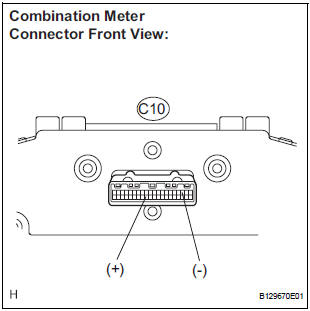
- Connect the positive (+) lead from the battery terminal 32 and negative (-) lead to terminal 3, and check that the indicator light comes on.
OK: Indicator light comes on.
7 CHECK HARNESS AND CONNECTOR (COMBINATION METER - FOLD SEAT CONTROL ECU)
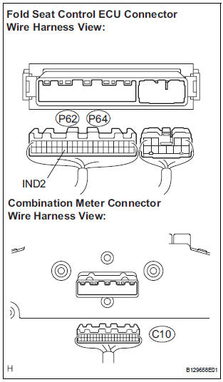
- Disconnect the connector from the fold seat control ECU.
- Measure the resistance according to the value(s) in the table below.
Standard resistance LH side

RH side
8 INSPECT COMBINATION METER (3rd SEAT INDICATOR LIGHT)
- Connect the positive (+) lead from the battery terminal 32 and negative (-) lead to terminal 3, and check that the indicator light comes on.
OK: Indicator light comes on.
PROCEED TO NEXT CIRCUIT INSPECTION SHOWN IN PROBLEM SYMPTOMS TABLE
 Back Door Courtesy Switch Circuit
DESCRIPTION
The fold seat control ECU receives signals from the back door courtesy switch
and detects the state of the
back door (open/close). If the ECU does not detect that the back door is open ...
 Power Source Circuit
DESCRIPTION
Power is supplied to the fold seat control ECU through the L-RR2 SEAT and
R-RR2 SEAT fuses.
WIRING DIAGRAM
INSPECTION PROCEDURE
1 INSPECT FUSE (L-RR2 SEAT, R-RR2 SEAT)
Re ...
Other materials:
“Contact/Call History Settings” screen
Display the “Phone/Message Settings” screen.
Select “Contact/Call History Settings”.
Select the desired item to be set.
For PBAP compatible
Bluetooth® phones, select to
set “Automatic Transfer” on/
off. When set to on, the
phone’s contact data and history
a ...
Inspection
1. INSPECT POWER STEERING RACK
(a) Using a dial indicator, check the power steering rack
for runout and for teeth wear and damage.
Maximum runout:
0.3 mm (0.012 in.)
If necessary, replace the rack & pinion power
steering gear assembly.
(b) Check the back surface for wear and damag ...
Reassembly
1. INSTALL INSTR PNL PASS L/DOOR AIR BAG
ASSEMBLY
2. INSTALL INSTRUMENT PANEL WIRE NO.2
3. INSTALL NAVIGATION ANTENNA ASSEMBLY
4. INSTALL ANTENNA CORD SUB-ASSEMBLY
5. INSTALL INSTRUMENT PANEL BOX DOOR SUBASSEMBLY
NO.2
6. INSTALL INSTRUMENT PANEL FINISH PANEL
RETAINER NO.1
7. INSTALL INSTRUM ...