Toyota Sienna Service Manual: Short to B+ in Front Passenger Side Squib 2nd Step Circuit
DTC B1188/56 Short to B+ in Front Passenger Side Squib 2nd Step Circuit
DESCRIPTION
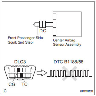
The front passenger side squib 2nd step circuit consists of the center airbag sensor assembly and the front passenger airbag assembly.
The circuit instructs the SRS to deploy when deployment conditions are met.
DTC B1188/56 is recorded when a short to B+ is detected in the front passenger side squib 2nd step circuit.

WIRING DIAGRAM
INSPECTION PROCEDURE
HINT:
- Perform the simulation method by selecting the "check mode" (signal check) with the intelligent tester.
- After selecting the "check mode" (signal check), perform the simulation method by wiggling each connector of the airbag system or driving the vehicle on a city or rough road
1 CHECK FRONT PASSENGER AIRBAG ASSEMBLY (FRONT PASSENGER SIDE SQUIB 2ND STEP)

- Turn the ignition switch to the LOCK position.
- Disconnect the negative (-) terminal cable from the battery, and wait for at least 90 seconds.
- Disconnect the connectors from the front passenger airbag assembly.
- Connect the black wire side of SST (resistance 2.1 Ω) to
the instrument panel wire.
CAUTION: Never connect a tester to the front passenger airbag assembly (front passenger side squib 2nd step) for measurement, as this may lead to a serious injury due to airbag deployment.
NOTICE: Do not forcibly insert the SST into the terminals of the connector when connecting.
Insert the SST straight into the terminals of the connector.
SST 09843-18060
- Connect the negative (-) terminal cable to the battery, and wait for at least 2 seconds.
- Turn the ignition switch to the ON position, and wait for at least 60 seconds.
- Clear the DTCs stored in memory.
- Turn the ignition switch to the LOCK position.
- Turn the ignition switch to the ON position, and wait for at least 60 seconds.
- Check the DTCs.
OK: DTC B1188/56 is not output.
HINT: Codes other than DTC B1188/56 may be output at this time, but they are not related to this check.
REPLACE FRONT PASSENGER AIRBAG ASSEMBLY
2 CHECK INSTRUMENT PANEL WIRE (FRONT PASSENGER SIDE SQUIB 2ND STEP CIRCUIT)

- Turn the ignition switch to the LOCK position.
- Disconnect the negative (-) terminal cable from the battery, and wait for at least 90 seconds.
- Disconnect the SST (resistance 2.1 Ω) from the instrument panel wire.
- Disconnect the connector from the center airbag sensor assembly.
- Connect the negative (-) terminal cable to the battery, and wait for at least 2 seconds.
- Turn the ignition switch to the ON position.
- Measure the voltage according to the value(s) in the table below.
Standard voltage

3 CHECK CENTER AIRBAG SENSOR ASSEMBLY
- Turn the ignition switch to the LOCK position.
- Disconnect the negative (-) terminal cable from the battery, and wait for at least 90 seconds.
- Connect the connectors to the front passenger airbag assembly and the center airbag sensor assembly.
- Connect the negative (-) terminal cable to the battery, and wait for at least 2 seconds.
- Turn the ignition switch to the ON position, and wait for at least 60 seconds.
- Clear the DTCs stored in memory.
- Turn the ignition switch to the LOCK position.
- Turn the ignition switch to the ON position, and wait for at least 60 seconds.
- Check the DTCs.
OK: DTC B1188/56 is not output.
HINT: Codes other than DTC B1188/56 may be output at this time, but they are not related to this check.
USE SIMULATION METHOD TO CHECK
 Short to GND in Front Passenger Side Squib
2nd Step Circuit
Short to GND in Front Passenger Side Squib
2nd Step Circuit
DTC B1187/55 Short to GND in Front Passenger Side Squib
2nd Step Circuit
DESCRIPTION
The front passenger side squib 2nd step circuit consists of the center airbag
sensor assembly and the
front p ...
 Short in Rear Curtain Shield Squib RH Circuit
DTC B1630/83 Short in Rear Curtain Shield Squib RH Circuit
DESCRIPTION
The rear curtain shield squib RH circuit consists of the center airbag sensor
assembly and the curtain
shield airbag assembl ...
Other materials:
Diagnosis system
1. CHECK DLC3
(a) The vehicle's ECM uses the ISO 15765-4 for
communication. The terminal arrangement of the
DLC3 complies with SAE J1962 and matches the
ISO 15765-4 format.
HINT:
Connect the cable of the intelligent tester to the
DLC3, turn the ignition switch to the ON position
and atte ...
Disassembly
1. REMOVE REAR SEAT LEG COVER LH
Remove the 2 screws and seat leg cover.
2. REMOVE REAR SEAT LEG COVER RH
Remove the 2 screws and seat leg cover.
3. REMOVE REAR SEAT LEG SIDE COVER LH
Remove the 2 screws and leg side cover.
4. REMOVE LH SEAT REAR SEAT LOCK COVE ...
Engine Control System Malfunction
DTC C1201/51 Engine Control System Malfunction
DESCRIPTION
If trouble occurs the engine control system, the ECM transmits the
abnormality to the skid control ECU.
The skid control ECU set this DTC and the skid control ECU prohibits TRAC and
VSC control.
INSPECTION PROCEDURE
1 CHECK ENGIN ...